Install pivot tubes – Great Plains NTA3007HD Operator Manual User Manual
Page 7
Install Welded Parts
Great Plains Manufacturing, Inc.
7
02/21/2012
166-367M
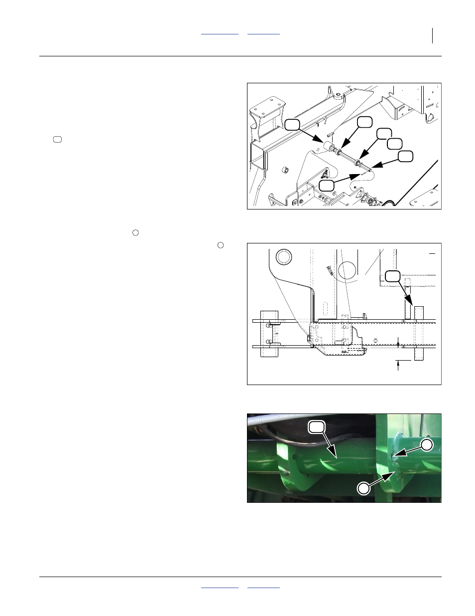
Install Pivot Tubes
Start with the right side of the implement.
Refer to Figure 10, Figure 11and Figure 12
38. Remove paint from the frame around the former
bearing mount holes.
39. Select one new:
Insert the tube through the frame holes where the
previous pivot shaft was removed.
40. Adjust the tube position for a reveal of 81.0 mm
(3.10 in) on the outside of the frame (left reveal on
left side; right reveal on right side). Tack weld the
tube. Recheck the reveal.
41. At the outside face of the outside frame plate, and
the inside face of the inside frame plate, weld the
contact circumference of the tube/frame joints with a
9 mm (
3
⁄
8
in) weld fillet
.
Note: It is not necessary to fill the former bolt holes
during welding.
42. Repeat step 38 through step 41 for the left side.
43. Wait for the welds to cool.
44. At all welds, remove welding residue and any
charred paint. Apply matching green paint.
45. Allow paint to dry.
Figure 10
Pivot Tube and Bearings
29379
.epsi
100%
Figure 11
Pivot Tube Placement
32067
(3.19 in)
81.0 mm
4
Figure 12
Pivot Tube Weld
32067
5
6