Caution – Great Plains FCP1000 Predelivery Manual User Manual
Page 8
6
FCP1000 Three-Meter Drill and Hitch 148-693Q
11/4/08
Great Plains Mfg., Inc.
4.
Turn cylinders to a position where rod ends are higher
than base ends. Support cylinders in a safe location.
5.
Start tractor and run engine at idle speed. With rod
ends higher than base ends, hydraulically extend cyl-
inders. After cylinder rods are fully extended, continue
to hold control lever for one minute before hydrauli-
cally retracting cylinders.
6.
Repeat step 5 three times to completely bleed system.
If air is still trapped in either cylinder, it will operate in
jerky, erratic motions. Repeat steps until cylinder
movement is smooth and even.
7.
Repin cylinders to hitch frame. Reinstall short com-
pression springs on cylinder-support-brace bolts and
re-tighten 1/2” nylock nuts until springs are com-
8.
pressed to 32 mm (1 1/4”). If for any reason the 1/2”
jam nuts in centre of support-brace bolts were
changed, refer to Transport Cylinder Support Brace in
the operator’s manual for proper adjustment.
9.
Refill tractor hydraulic-fluid reservoir to proper level.
Bleeding Marker Hydraulics
!
CAUTION!
You may be injured if hit by a folding or unfolding marker.
Markers may fall quickly and unexpectedly if the hydraulics fail.
Never allow anyone near the drill when folding or unfolding the
markers.
1.
Check that tractor hydraulic reservoir is full.
2.
With both markers lowered into field position, loosen
hydraulic-hose fittings at rod and base ends of marker
cylinders. Loosen fittings on back side of sequence
valve.
3.
With tractor idling, activate tractor hydraulic valve until
oil seeps out around a loosened fitting. Tighten that fit-
ting.
4.
Reactivate tractor hydraulic valve until oil seeps out
around another loosened fitting. Tighten that fitting.
Repeat process until all loosened fittings have been
bled and tightened.
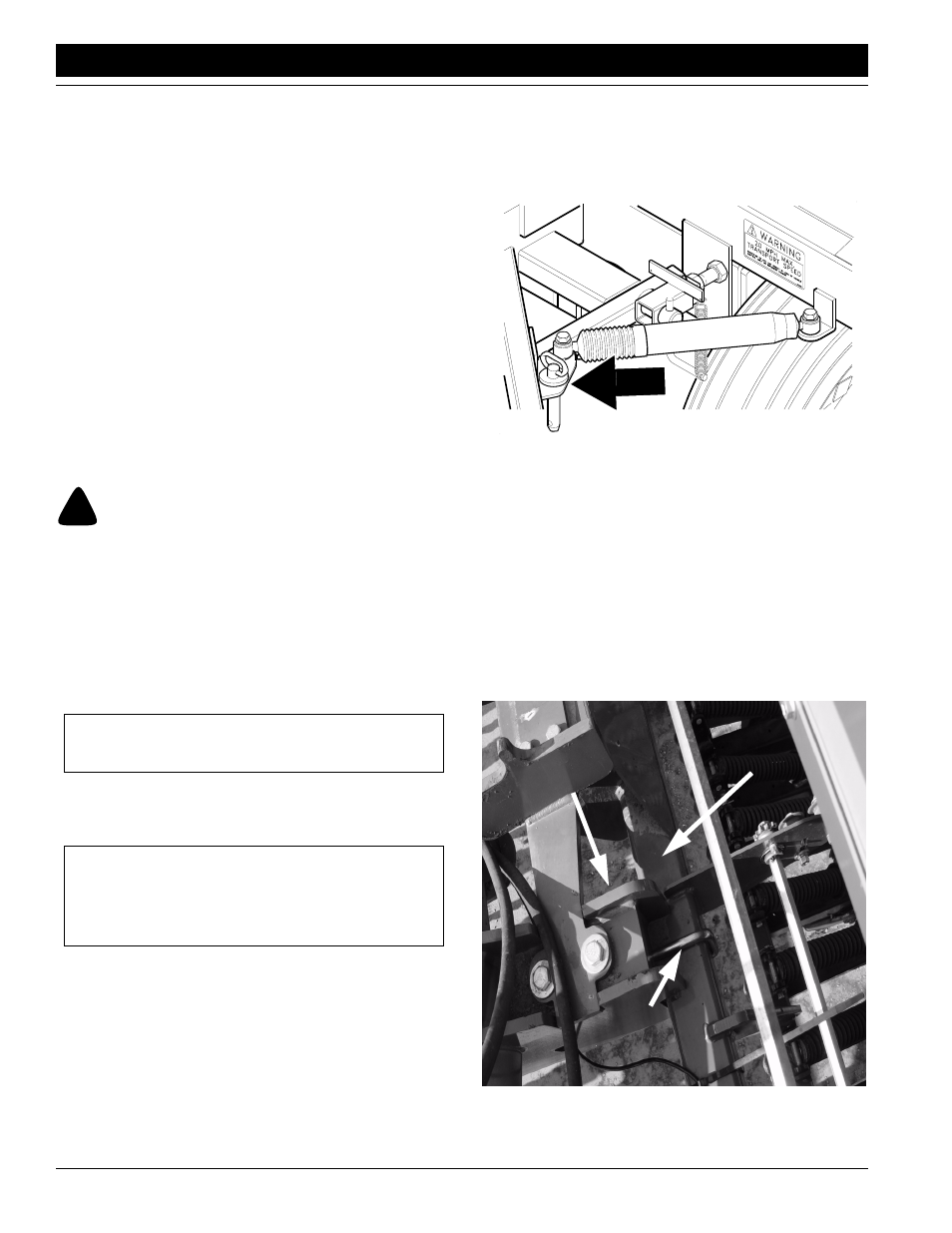
Refer to Figure 3
5.
With center-pivot hitch properly secured to tractor
drawbar, remove transport lock pins located in vertical
tubes above tires and place in storage hole next to sta-
bilizer cylinder on hitch as shown.
Figure 3
Transport Pins in Storage
6.
Position the center pivot hitch in front of drill. Use the
transport-lift cylinders to vertically align the main
frame clamp plates with the drill box frame.
Refer to Figure 4
7.
Center the main frame clamp plates with the box
frame. Attach the box frame to the main frame clamp
plates with two 3/4” x 6” x 5 5/8” U-bolts, 3/4” flat wash-
ers, 3/4” lock washers and 3/4” nuts.
Figure 4
Attaching Frames
IMPORTANT: Never bleed an O-ring fitting. Instead,
bleed a nearby pipe or JIC fitting.
IMPORTANT: JIC fittings do not require high torque.
JIC and O-ring fittings do not require sealant. Always
use liquid pipe sealant when adding or replacing pipe-
thread fittings. To avoid cracking hydraulic fittings from
over tightening, do not use plastic sealant tape.
12081
21616
Box Frame
Main Frame
Clamp Plate
U-Bolt