Setting relief valve, Strainer – Great Plains YP1625 Material Rate User Manual
Page 62
Great Plains Mfg., Inc.
58
401-263B
11/23/2011
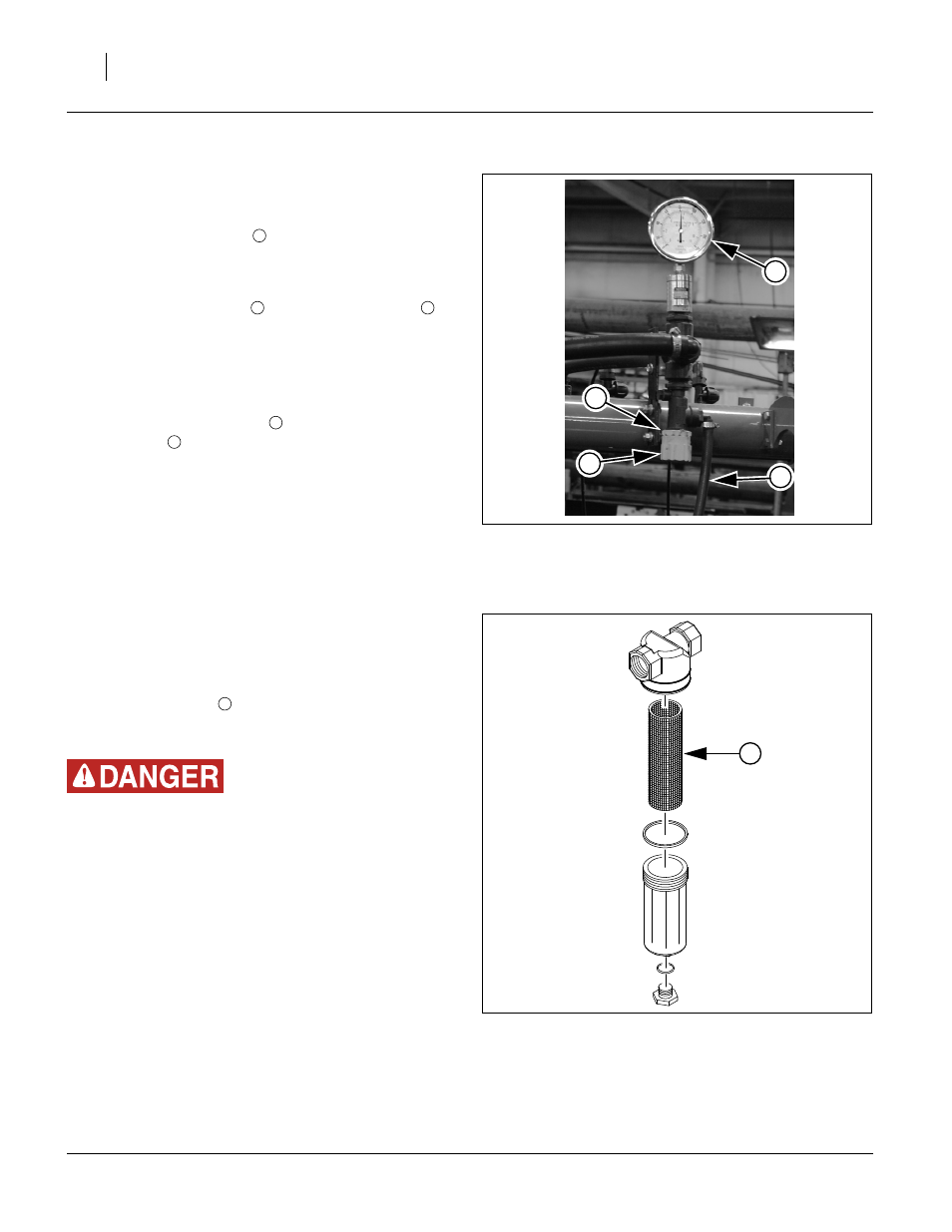
Setting Relief Valve
A relief valve is mounted directly above the pump to pro-
tect the manifold and pump from excessive pressure.
Any product that dumps over the relief valve will dis-
charge from the dump line
To set relief valve:
Unlock plastic jam nut
from relief valve knob
2.
Unscrew knob clockwise until it loses contact with
internal spring.
3.
Screw knob counterclockwise two turns. Start at this
setting.
4.
Observe manifold gauge
. Watch for relief valve
discharge
while operating in the field.
5.
If valve is dumping product and gauge reads under
65 psi, stop tractor and, looking down, turn knob
clockwise
1
⁄
4
turn. Continue operating at normal field
speed. Repeat this step as needed until no product
is discharged from relief valve.
6.
If pressure gauge reads above 65 psi, change to a
larger orifice. Go to step 2. Repeat steps.
Strainer
Refer to Figure 20
A Banjo brand strainer is supplied with the fertilizer pump
option. It is plumbed before the Hypro pump. The stan-
dard 80 mesh screen
should be suitable for most
applications. Other screen sizes are available from Banjo
Corporation.
Wear protective gloves when changing screens.
If changing screen sizes, keep in mind the following.
• A smaller mesh (100) will keep very small manifold ori-
fice plates from plugging so often. However, the
screen will have to be cleaned more often.
• A larger mesh (50) or (30) will pass more material but
should only be considered when using large manifold
orifice plates.
• A plugged or partially plugged screen will starve the
pump resulting in a reduced application rate.
• Mesh sizes: (Smallest) 100, 80, 50, 30 (Largest)
Figure 19
Pressure Relief Valve
28029
2
3
4
1
1
3
4
Figure 20
Strainer
18418
5
5