Great Plains Verti-Till Ripper VT 03 Hyddepth Convert User Manual
Page 3
11/29/2004
596-141M
Great Plains Mfg., Inc.
3
Installation Instructions
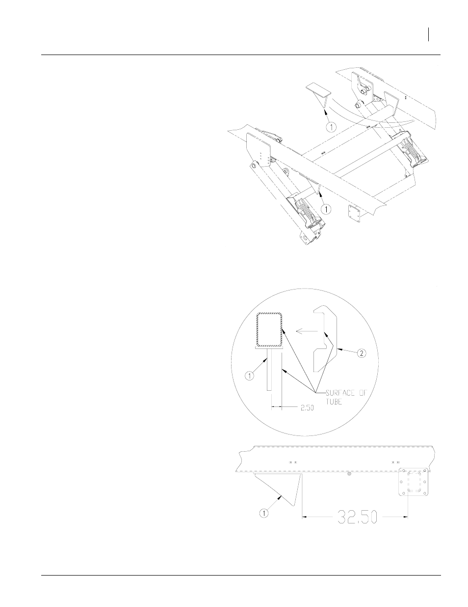
Refer to Figure 4
8.
Clamp the bumper sub weldments (1) to the
implement frame directly above the torque
tube depth stop weldment. Orientate the
bumper (1) with the taper facing towards the
rear of the implement.
Refer to Figure 5
9.
Place the bumper (1) so the inside surface is
2 1/2" from the inside surface of the frame
tube. To assure this use the weld gage (2).
Slide the gage (2) along the entire surface of
the bumper (1) making sure the bumper is
straight with the frame.
10. Tap the bumper (1) forward or backward until
the front surface of the base plate measures
32 1/2" from the inside surface of the forward
cross tube of the implement frame.
11. Recheck the placement of the bumper (1)
with the weld gage (2) making sure the
bumper is straight. Make sure the clamp is
tight and then recheck measurements again.
12. Tack weld the bumper (1) to the implement
frame in several places. Place the welding
ground as close to the welding area as possi-
ble, preferably on the bumper (1) itself. This
will assure that no arcing will take place
through any bearings or pivot points.
13. Remove the transport locks and lower the unit
down to check for clearance and function.
NOTE: It may be necessary to adjust the hydraulic
stop paddle to a deep setting to allow implement
enough travel to check for clearance.
14. Raise implement and reinstall the transport
cylinder locks.
15. Finish welding the bumpers to the frame.
Weld along each side and across the front
and back of each bumper.
16. After the weld has cooled, repaint the surface
with the spray paint provided with the kit.
Figure 4
Bumper Sub weldment
22803
Figure 5
Welding Placement
22807