Assembly instructions – Great Plains 4000TM User Manual
Page 2
Great Plains Manufacturing, Inc.
2
04/09/2013
586-541M
Assembly Instructions
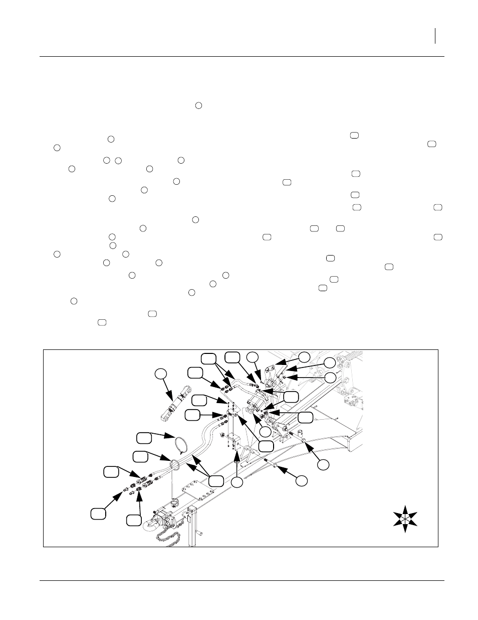
Note: Move machine to level ground and lower machine
until pressure is off of hitch turnbuckle
.
Refer to Figure 2
1.
Remove the 1 top lock nuts from the 1 x 6, Gr. 8 spe-
cial thread bolt
and 1 x 8 Gr. 8, special thread bolt
.
2.
Remove bolts
,
and turnbuckle
and the 3/8
bolt
from cylinder clevis
.
3.
Install the 586-849D valve bracket
and base end
of the 810-626C cylinder
with the 1 x 6, Gr. 8 spe-
cial thread bolt
secure with the same 1 top lock
nut. Torque bolt to 910ft-lb.
4.
Install rod end of the 810-626C cylinder
and the
589-487H level indicator
with the 1 x 8, Gr. 8 spe-
cial thread bolt
. Secure with the same 1 top lock
nut. Torque bolt
to 910ft-lb. Re- install the 3/8 bolt
to cylinder clevis
and small hole of 589-487H
level indicator
. Torque bolt
to 31ft-lb.
5.
Remove the two nuts
from rod end of cylinder
and install the 589-222D level gauge bracket
in
position shown. Re-install the two nuts
. Tighten
nuts
snug.
6.
Install 810-599C lock valve
with three, 802-152C,
1/4 x 2 bolts
, 1/4 lock washers and 1/4 nuts.
Tighten bolts to 8ft-lb.
Note: Be sure ports in cylinders, valves, all fittings and
hose ends are clean before installing fittings if fit-
tings are not installed. If fittings and hoses are
connected to valve and cylinder go onto step 10.
7.
Install two, orrifice plates
into cylinder ports
(groove side out). Install two, 90 degree elbows
into cylinder ports, turn to desired angle for best
hose routing and tighten jam nut.
8.
Install four straight fittings
into all four ports of lock
valve
. Tighten fittings.
9.
Install the two, 13” hoses
. Tighten hoses.
10. Install the two 108” hoses
to front of lock valve
and tighten hoses.
11. Install fittings
and
to other end of 108” hoses
and tighten fittings. Install yellow hose handles
over fittings.
12. Route 108” hoses
along existing hoses to front of
hitch and through spring hose loop
to tractor.
13. Secure 108” hoses
to existing hoses with the 800-
112C cable ties
.
14. Be sure all fittings and hoses are tight, hook hoses to
tractor and retract and extend cylinder several times
to purge of air and check for leaks.
3
1
2
1
2
3
4
4
5
6
1
6
7
2
2
4
6
7
4
8
6
9
8
8
10
11
12
13
14
10
15
16
10
17
18
16
19
16
20
16
21
U
D
F
B
L
R
3
Null4:
Figure 2
Hydraulic Remote Leveling Assembly
42972
6
1
5
2
12
21
14
7
9
18
17
19
16
15
4
11
13
10
13
20
8
14