Functions and operation – Monarch Instrument SPSR-230 User Manual
Page 6
3
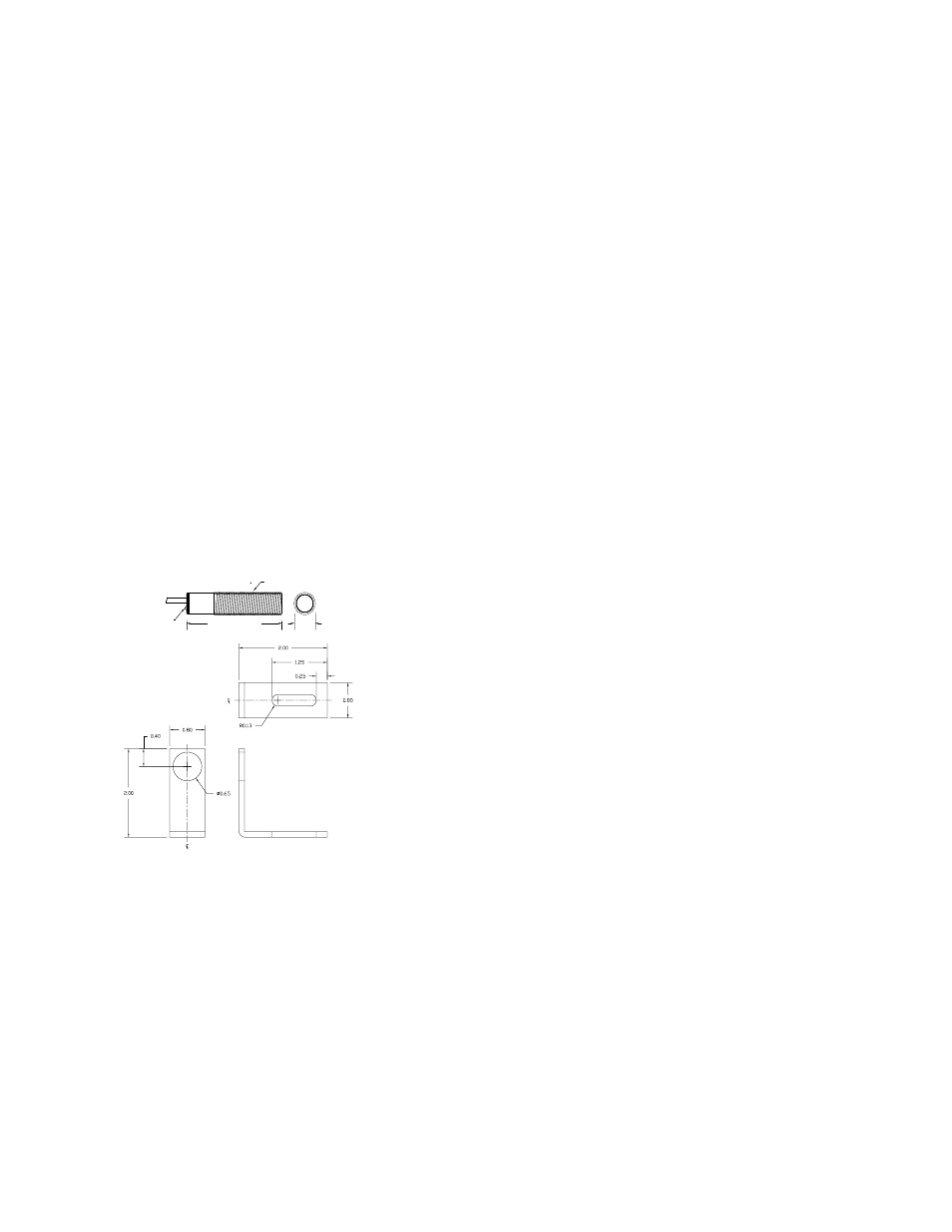
ROS-P Remote Optical Sensor
Operating Envelope: Up to 3 feet [0.9 m] and 45
°
from refl ective target
Speed Range:
1 to 250,000 RPM
Illumination Source:
Visible red LED, 5 Vdc @ 30 mA
Operating Temp:
14° F to 158° F [-10° C to 70° C]
Output Signal:
5 to 0 Vdc TTL compatible pulse
On-Target Indicator: Green LED on end cap
Material:
303 Stainless steel
Lens:
Acrylic plastic
Cable Length:
8 feet [2.5 m] Standard
Dimensions:
Threaded Tube - 2.90” L x 0.625 “ diameter [M16
x 1.5 x 74 mm] supplied with two M16 jam nuts
and mounting bracket
M16 x 1.5
Green
On Target LED
0.62” [15.9mm]
2.90” [74.0mm]
ROS-P and mounting bracket Dimensions
4
FUNCTIONS AND OPERATION
SPSR Interface Module
The SPSR Interface Module (SPSR-IM) provides power to the input
sensor, receives and optionally inverts the return pulse signal, and provides
a switch selectable positive going 0 to 5 Vdc or negative going 5 to 0 Vdc
pulse train trigger output on a BNC connector. Connections and operation
are common to all SPSR models. Fully charged internal NiMH batteries will
typically provide greater than 40 hours of continuous operation. In addition,
the SPSR system can be operated continuously on external power by use of
the recharger/power supply or cable provided.
Connections
Connect the input sensor via the 1/8” [3.5 mm] phone plug to the mating
connector on the SPSR-IM. This sensor may remain connected even
when recharging the internal batteries of the SPSR-IM.
Connect the output signal cable to the BNC connector on the opposite
end of the SPSR-IM and to the external equipment to be triggered.
If operating from the recharger/power supply, connect the recharger
to the connector marked “External DC” on the SPSR-IM and connect
the wall unit to the appropriate power source. When using the CA-
DCSPSR cable, connect the cable to the connector marked “External
DC” on the SPSR-IM and connect the cigarette lighter connector to
the appropriate power source.
Controls
The “Power” switch on the SPSR-IM controls both the operation and the
charging of the system. The unit will only charge from external power
in the power OFF position. In the power ON position, the unit will