Introduction, Component specifications – Monarch Instrument SPSR-230 User Manual
Page 4
1
INTRODUCTION
The SPSR-IM Self Powered Sensor Interface Module is a self-contained,
rechargeable battery powered device for developing a TTL compatible one
pulse per revolution output for triggering external equipment such as vibration
analyzers, spectrum analyzers, stroboscopes, data acquisition equipment,
tachometers, balancers, waveform analyzers and magnetic tape recorders.
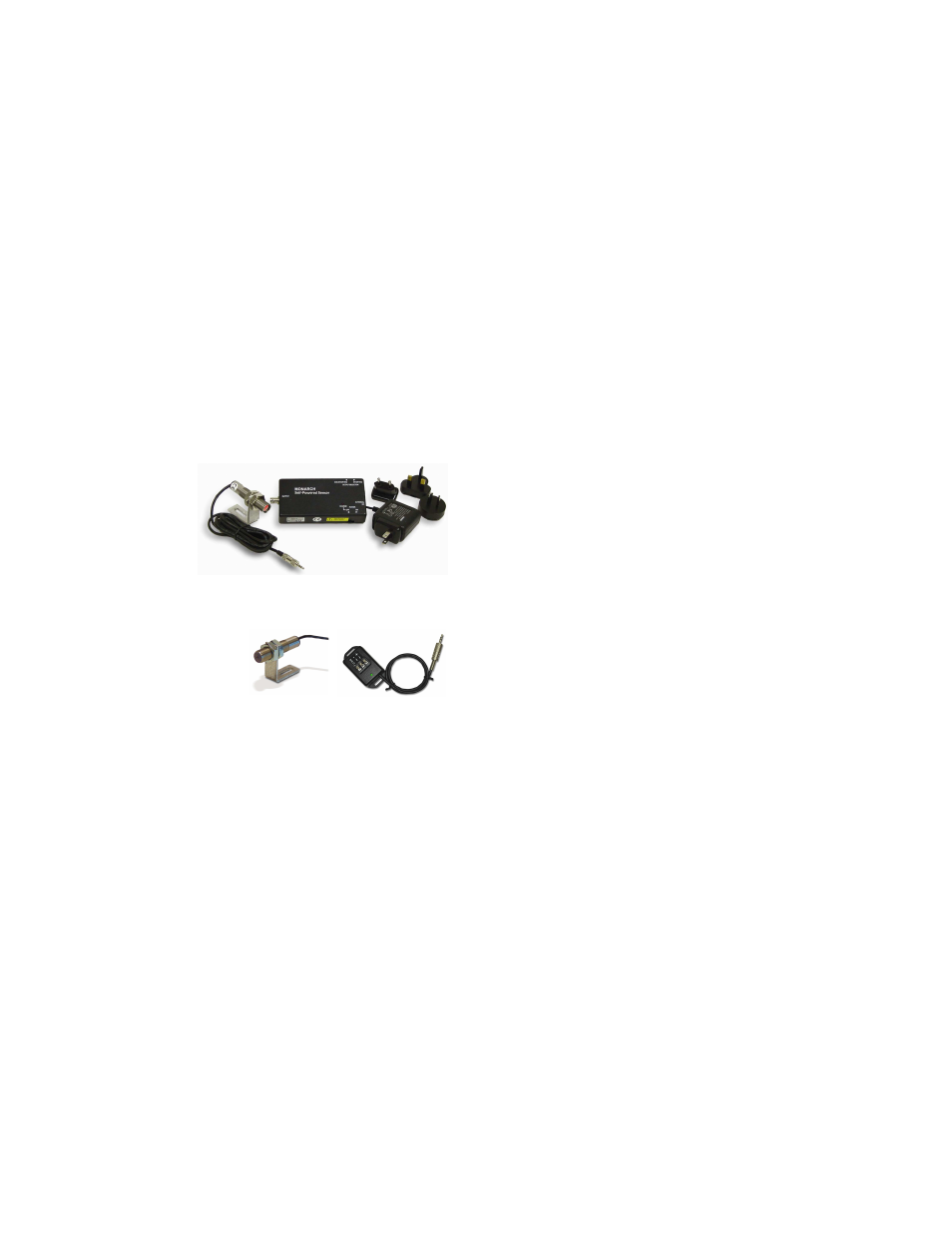
T h e S P S R - 11 5 / 2 3 0 i s
comprised of the SPSR-IM
Interface Module, which
provides power to a sensor
and couples the sensor to
a BNC output; an input
sensor with a visible red
LED light source (ROS-P);
and a battery recharger.
Optional sensors such as an optical
laser sensor (ROLS-P-not shown),
infrared sensor (IRS-P), or an
amplified magnetic sensor (MT-
190P) may also be combined with the
SPSR-IM Interface Module when
appropriate. (See separate instructions for these confi gurations.)
COMPONENT SPECIFICATIONS
SPSR-IM Interface Module
Internal Batteries:
Nickel Metal Hydride (NiMH) Battery Pack, 4.8 Vdc
Operating Interval: >40 hours typical with ROS-P (~40mA load)
Charge Time:
up to 4 hours
SPSR-115/230
(SPSR-IM, ROS-P and Universal Recharger)
MT-190P
Magnetic Trigger Sensor
IRS-P
Infrared Sensor
6
SPSR-115/230 Series - SPSR-IM with ROS-P
The SPSR-115/230 consists of the SPSR-IM Interface Module described
above, an ROS-P Remote Optical Sensor with eight foot cable and mounting
bracket, and a PSC-2U (115/230 Vac) external power connection. One foot
of T-5 Refl ective Tape is also supplied.
ROS-P
When connected to the SPSR-IM as described above, the ROS-P
illuminates the target with a visible red light from a high intensity LED
and detects the refl ected pulses from the rotating refl ective tape target
with an internal photo-detector. The ROS-P Remote Optical Sensor is
capable of detecting a refl ected pulse from T-5 Refl ective Tape targets
at distances of up to 3 feet and angles up to 45 degrees from the target.
The sensor is supplied with a set of two M16 jam nuts and a 90° angle
slotted aluminum mounting bracket.
For most applications, a 1/2” square piece of T-5 Refl ective Tape should
be applied to a clean area on the rotating object. The sensor should be
mounted and optically aligned to illuminate the refl ective target once per
revolution. It is recommended that the optical sensor be placed at a
slight angle (approximately 10-15 degrees) from perpendicular, so
that the sensor will detect only the refl ected pulses from the target.
The sensor should be at least 2 inches and no more than 3 feet from the
target. The green LED On-Target Indicator on the ROS-P will blink at
the input frequency or be continuously illuminated when properly aimed.
Operating the SPSR as a triggering source
Once the ROS-P input sensor is properly mounted and aligned, further
connections and operation should proceed in accordance with the
functions and descriptions under the SPSR Interface Module sections
entitled ‘Connections’ and ‘Controls’.