Installation instructions, Step 1, Step 2 – Quoizel GF1717AN Griffin User Manual
Page 2: Step 3, Step 4
INSTALLATION INSTRUCTIONS
STYLE NUMBER GF1717AN,GF1717PN
:
2 OF 3
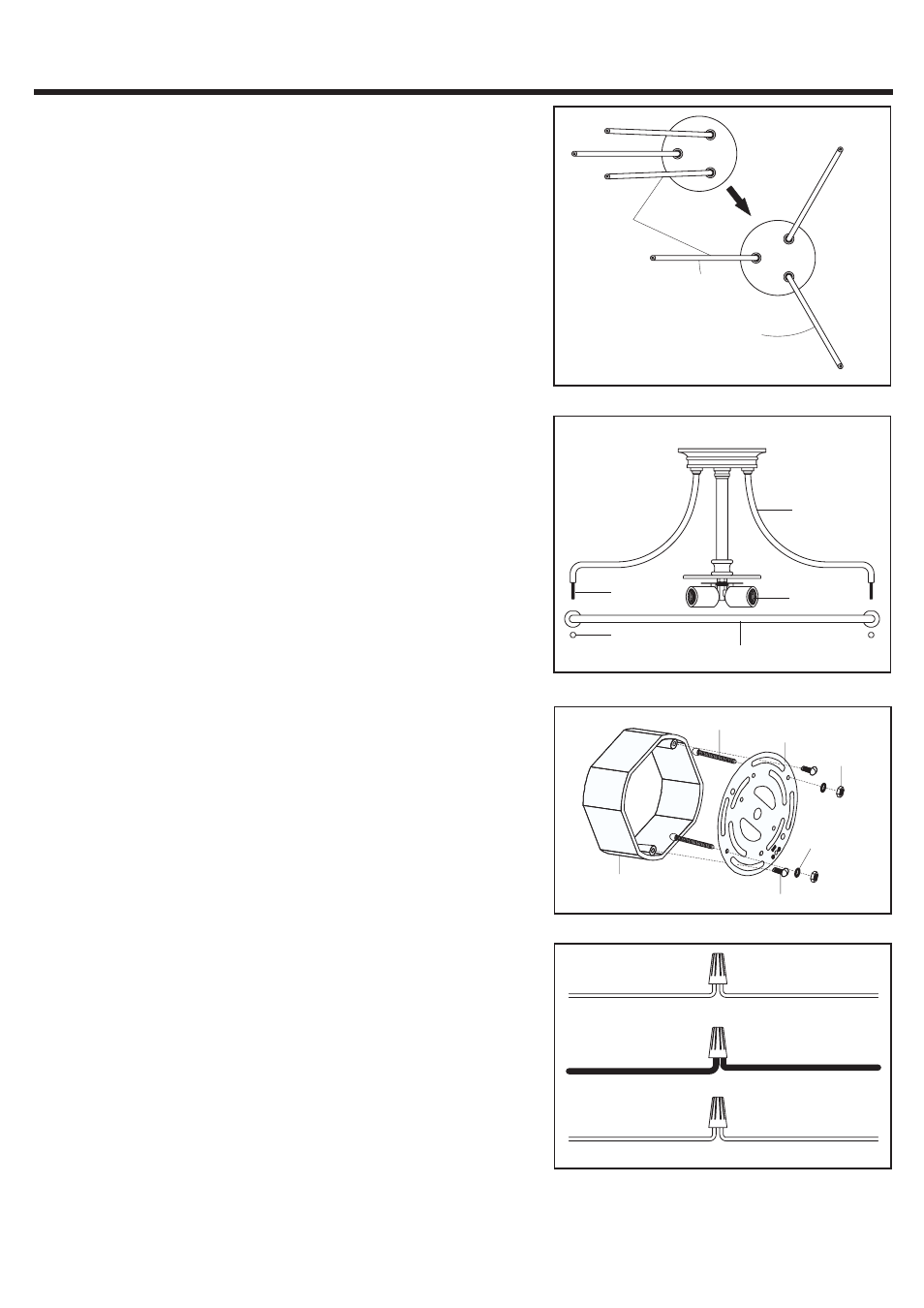
STEP 1:
a Unfold Support Arms at 120 degree locations as shown.
.
STEP 2:
a Locate the holes on the Ring over the Bolts on the ends of
Support Arms. Secure by threading Lock Balls onto the
Bolts. Hand tighten until snug.
.
120
Degree
Support
Arm
Support Arm
Socket
Assembly
Lock Ball
Ring
Bolt
STEP 3:
a Screw the Mounting Screws into the Crossbar
place the
Lock Washers over the Mounting Screws and thread the
Hex Nuts onto the Mounting Screws as shown
Secure the
position of the Mounting Screws by tightening the Hex Nuts
against the Crossbar
b
Secure the Crossbar to the Outlet Box with Outlet Box
Screws
.
,
.
.
.
.
Outlet Box
Crossbar
Mounting Screw
Hex Nut
Outlet Box Screw
Lock Washer
WHITE OR RIBBED
BLACK OR RED WIRE
(
)
FROM HOUSE
GROUND WIRE
GROUND WIRE
FROM HOUSE
FROM FIXTURE
WHITE OR RIBBED
FROM FIXTURE
FROM HOUSE
FROM FIXTURE
BLACK OR SMOOTH
STEP 4
:
*
(
)
.
.
.
(
)
(
)
.
(
)
(
).
.
.
Use Wire Connectors not supplied to connect the
wires
a
Connect the House Ground Wire to the Fixture Ground
Wire.
b
Connect the House White
or Ribbed
Wire to the
Fixture Supply Wire White or Ribbed Side .
c Connect the House Black or Red
Wire to the Fixture
Supply Wire Black or Smooth Side
d Wrap each connection with approved electrical tape and
carefully stuff all of the connected wires into the Outlet Box