Battery backup unit, Warning caution warning warning – Chamberlain WD952LD User Manual
Page 32
To prevent possible SERIOUS INJURY or DEATH from
electrocution, disconnect power to motor unit BEFORE
proceeding.
WARNING
CAUTION
WARNING
WARNING
Mounting the battery backup unit (BBU) can be
done using one of two methods. The BBU can be
mounted directly on top of the motor unit or it can be
secured on a structural support just above it.
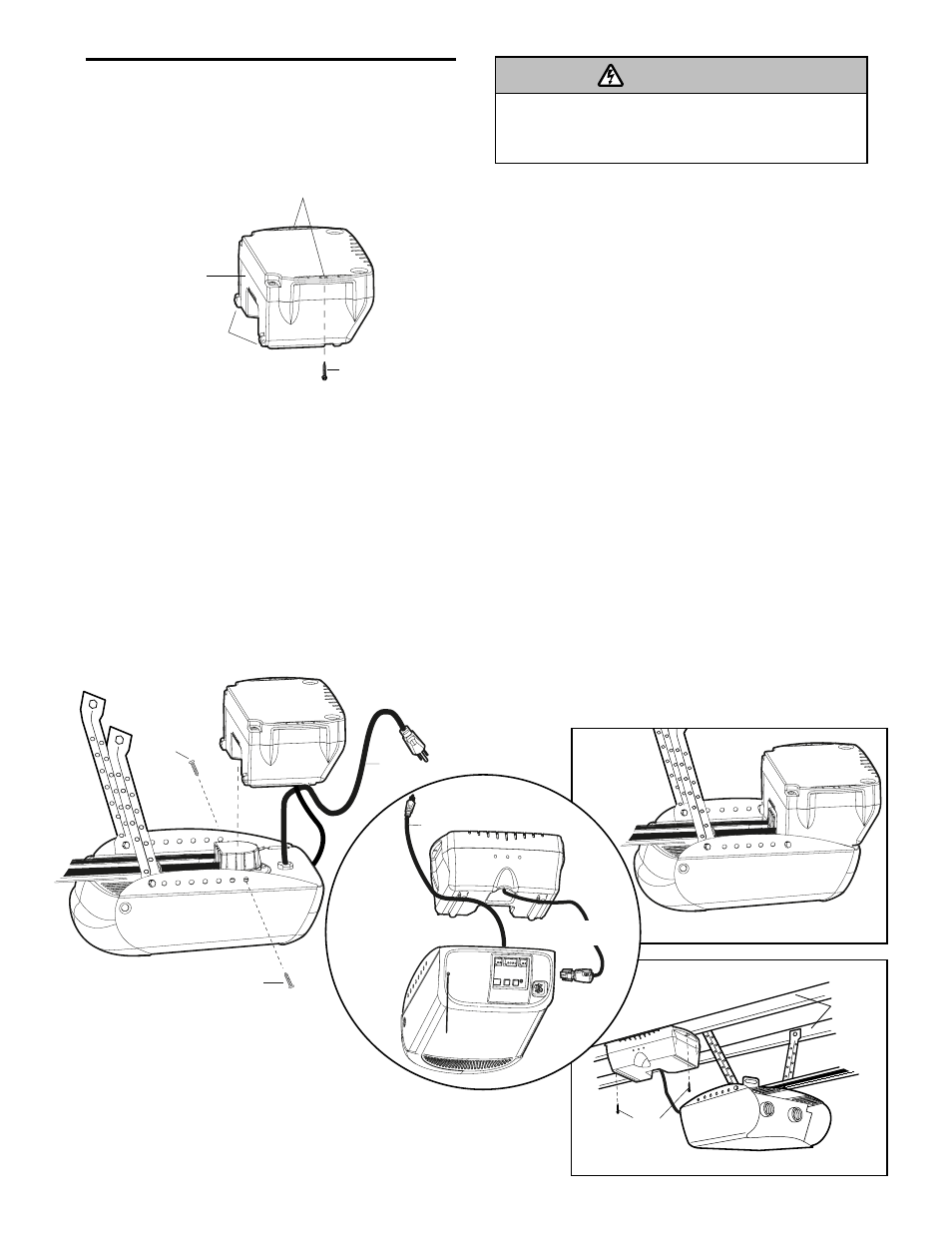
1. Mounting the BBU Directly to the Motor Unit.
• Position the BBU on top of the motor unit. Make
sure the motor unit power cord is drawn out from
beneath the BBU. The BBU should sit firmly on top
of the motor unit. Adjust angle iron placement so
that it is out of the way of the BBU’s installation
(Figure 1).
• Align the two screw slots on the BBU to the back
chassis holes.
• Secure the BBU to each side of the chassis
flanges with 3/4" screws provided.
Holes for Ceiling Mount
Side Screw
Slots for
Chassis Mount
Battery Backup
Unit (BBU)
Lag Screw
1-1/2"
2. Mounting the BBU Directly to the Ceiling
Structural Support.
• After the motor unit has been installed, position the
BBU above the motor unit to a structural support
(joist) within BBU’s cord length of 3' (.91 m)
(Figure 2).
• Attach the BBU to the support by using the ceiling
mount holes on either side of the BBU.
• Secure the BBU to the ceiling using 1-1/2" lag
screws (provided).
3. Connect the BBU to the Motor Unit.
• Disconnect the motor unit from the electrical outlet.
• Connect the BBU cord into the connector on the
right side of the end panel on the motor unit.
Connect the motor unit into the electrical outlet.
The BBU will activate and all LEDs will turn on for
3 seconds.
• The green LED will begin flashing indicating the
BBU is charging from the motor unit.
IMPORTANT NOTE: Installation of BBU when
permanent electrical power is not available (such as
new construction and the electricity is not installed)
may damage the batteries. Unplug BBU after testing
to prevent damage.
Lag Screws
1-1/2"
Structural
Supports
3/4" Screw
3/4" Screw
Power
Cord
Power
Cord
Antenna
BBU
Connector
➡
➡
Bring Power Cord
out left side slot
Bring BBU Cord out right
side slot away from Antenna
➡
Figure
1
Figure
2
BATTERY BACKUP UNIT
32