Quoizel TFIK1817VA Inglenook User Manual
Page 2
2of2
Thank you for purchasing a Quoizel product.
Need assistance with parts or assembly? Call Quoizel customer service at 1-631-273-2700
or visit us on-line at www.quoizel.com
2014 QuoizelInc.
August2014
D
and secure with Knurled Nut (C).
Tighten until snug.
B. Thread the Fixture Loop (A) onto
the Nipple at the top end of the
Socket Assembly (D) and hand
tighten until snug.
B
A
C
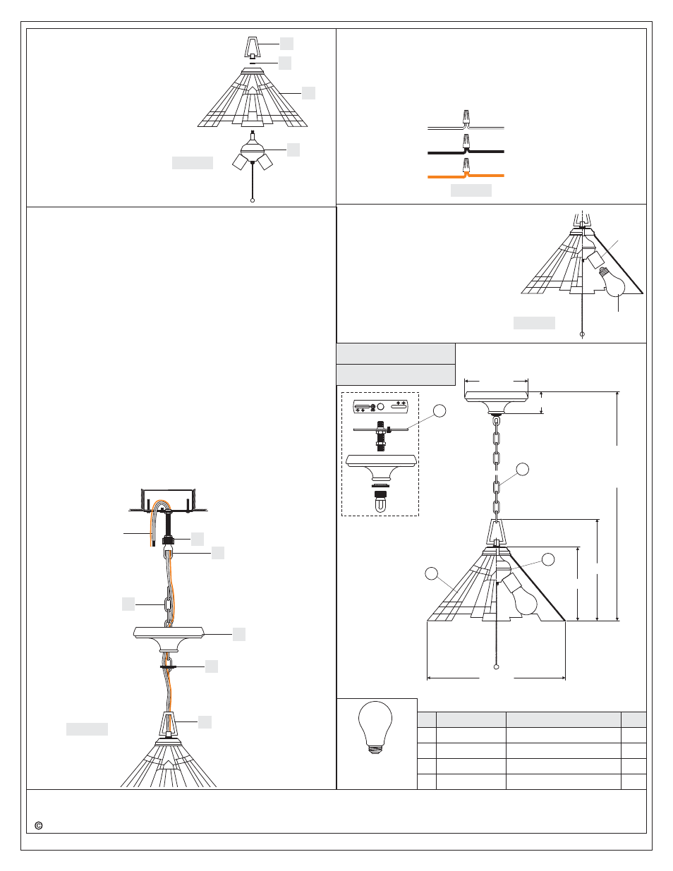
STEP 4 - Install Fixture Chain and Ceiling Canopy
A. Adjust the Fixture Chain (GG) to your desired length by removing
the links if needed.
Pliers is required for this step.
B. With the Fixture Chain (GG) not attached to the Fixture Loop and the
Canopy Chain Loop (EE), pull the supply wires through the Fixture
Chain (GG) alternating links. After the wires are through the Fixture
Chain (GG), pull the Supply Wires and the Ground Wire through the
Canopy Lock Ring (FF) and the Ceiling Canopy (HH) in order.
C. Attach one end of the Fixture Chain (GG) to the Fixture Loop. Lift the
fixture and Fixture Chain (GG) up and Attach the other end of the
Fixture Chain (GG) onto the Canopy Chain Loop (EE). The fixture
will now hang safely. Close the chain loop at the Ceiling Canopy
Loop (EE).
D. Feed the Supply Wires and Ground Wire through the Canopy Chain
Loop (EE) and Nipple (DD) into the Outlet Box. Cut the wires leaving
approximately 8” of wire extending from the Outlet Box.
E. Refer to Step 5 for wire connections.
F. Raise the Ceiling Canopy (HH) and Canopy Lock Ring (FF) up the
Fixture Chain (GG) and over the Canopy Chain Loop (EE). Tighten
the Canopy Lock Ring (FF) onto the Canopy Chain Loop (EE) until
tight.
Suggested chain length for Ceiling height :
8’ ceiling : use 16 links of chain
9’ ceiling : use 26 links of chain
10’ ceiling : use 36 links of chain
*
Figure 4
DD
GG
Supply Wires
and Ground Wire
EE
FF
A
STEP 5 - Wire Connections
A. Use standard wire connectors (not included) to make all wire
connections. (Connectors are not included with fixture.) Twist
connectors until wires are tightly joined together. Wrap each
connection with approved electrical tape and carefully stuff all the
connected wires into the Outlet Box.
White wire
from supply
Ribbed side wire
from fixture
Black wire from
supply (or Red)
Smooth side wire
from fixture
Ground wire
from supply
Ground wire
from fixture
Figure 5
STEP 6 - Install Bulb
A.
10
This fixture uses standard bulb with
medium base . Maximum
0 watts.
Insert bulb and screw snugly into place.
Your fixture is now assembled and ready
to use. Enjoy!
Bulb
Socket
Figure 3
Figure 6
TFIK1817VA
NOTE: ONE LIGHT SHOWN FOR
ILLUSTRATION PURPOSES ONLY.
FINISH: VALIANT BRONZE
(3)100W Medium
Bulbs
(Not Supplied)
Base
PART NUMBER
11817VATFIK
REPLACEMENT PART
BASE
NO.
1
REQ.
1
M1195CHVA
CHAIN
2
1
9”
12.5”
64.5” OVERALL
HEIGHT
INCLUDES
48” CHAIN
(
)
8” Dia.
3”
17” SQ.
J860KIT
MOUNTING HARDWARE
3
1
G2213SH
SHADE
4
1
NOTE: ALL DIMENSIONS ARE ROUNDED
UP TO THE NEAREST 1/2
"
1
2
3
4
HH