Calibration process, I t-dualscan – ORBIT FR T-DualScan User Manual
Page 7
124
Calibration process
The probe array system calibration allows for both
consistency in amplitude and in phase as well as the
radio-electric axis alignment of each probe. The calibration
procedure consists of the rotation of a reference antenna
along a roll axis in front of each probe. This is performed
with a dedicated calibration arm supporting the reference
antenna and its motorized roll axis. Mounted on one of
the linear axes of the scanner, the calibration arm moves
linearly to position the reference antenna in front of each
probe of the array.
Probe array
Number of
Probe array Scan area Number of probes
modules
length (cm)
(cm)
0.8 - 6 Ghz 6 - 18 Ghz
1
126 84 7 7
2
238 196 15 15
3
350 308 23 23
4
462 420 31 31
5
574 532 39 39
6
686 644 47 47
7
798 756 55 55
8
910 868 63 63
9
1022 980 71 71
10
1134 1092 79
79
11
1246 1204 87
87
12
1358 1316 95
95
• The distance between a 0.8 - 6 GHz and a 6 - 18 GHz probe is of 70 mm
• Distance between two 0.8 - 6 GHz probes: 140 mm
• Distance between two 6 - 18 GHz probes: 140 mm
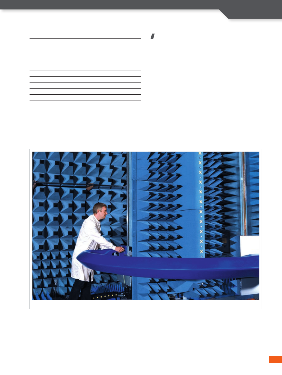
The engineer is mounting the arm for calibration
7
I T-DualScan