Standard system components, Linear probe array, Y axis scanner – ORBIT FR T-DualScan User Manual
Page 4: Antennas, X axis scanner, Absorbers and anechoic chamber, Dut positioning equipment, I t-dualscan
121
Standard system components
Linear probe
array
•
From 1 to 12 meters long
probe-array (StarLine)
It includes by default interleaved
probes to cover 0.8 to 18 GHz.
•
70 - 400 MHz probe array
available on demand
Y axis scanner
•
1 to 15 meter high tower scanner
•
Probe roll positioner
ORBIT/FR positioning
equipment catalog
Antennas
•
A complete range of measurement
probes (single or dual polarized)
and reference antennas (horns,
standard gain horns) are
available
MVG antenna catalog
X axis scanner
•
X Axis length depends
on customer requirement
Absorbers
and anechoic
chamber
•
An optimized combination of
standard, adapted and specialty
absorbers
•
Anechoic chamber with
integrated design, production,
installation and testing services
AEMI absorber catalog
DUT positioning
equipment
•
A complete range of rotary
positioners and model towers are
available with air cushion (optional)
ORBIT/FR positioning
equipment catalog
I T-DualScan
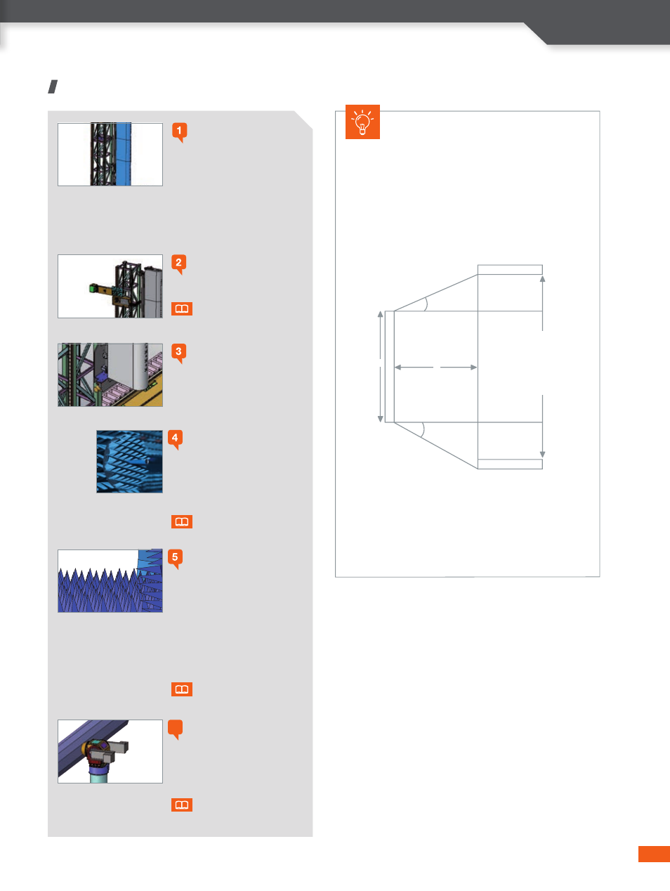
Quick guide to evaluate scan
area requirement
The required scan area is calculated according to the following
formula: Scan length = D + 2 L tg (
a
)
Where:
-
a
is the relevant data angle in far-field
- L, the distance between the probe and the AUT
- and D, the antenna size.
Sampling principle
Sampling step is based on the minimum measured
wavelength (
l
min
).
D
sampling
= (
l
min
/2)
Probe
Probe
L
Distance from
AUT to Probe
Scan Length
D
A
U
T
a
a
6
4
3