Weller DEC1001 User Manual
Page 2
Always use the lowest temperature that will handle the load you are soldering. The Weller
®
electronic control provides
maximum power to the heated load even when set to the lowest temperature; therefore, there is no need to use high
temperature to handle heavy soldering loads. By using lower temperatures and properly selecting tip styles, sensitive
components will be protected from heat damage.
WARNING:
Do not remove ground prong from line cord plug. Removal may cause tip temperature control
to be erratic.
SPECIFICATIONS
1. Power input: 120VAC, 60hz (240VAC ±10%, 50/60hz), 120 watts.
2. Power unit output voltage: isolated 24 VAC @ 3.4 amperes.
3. Size: 4.5" x 5.875" x 3.625".
4. Line Cord: 3 wire, U.L. recognized.
5. Tip temperature control range: 350°F to 850°F (175°C to 455°C
6. Control setting resolution: 10°F (5°C).
7. Control Accuracy: ±10°F (±6°C) of setting at idling temperature. No load and 30 minute warm-up.
8. Ambient temperature range: 60°F to 110°F (16°C to 44°C).
9. Line Voltage: 120VAC ±10% (240VAC ±10%).
MATERIALS NEEDED FOR CALIBRATION CHECK
The DEC1001 Soldering Station uses a high precision temperature sensor;
therefore, the soldering tools are interchangeable and cannot be calibrated.
The power unit is factory calibrated, but the calibration may be easily
checked using the following procedure. Two precision resistors, resistor A
(36.4 ±0.1 ohm, resistor B (51.4 ±0.1 ohm), and a 13 ohm 40 watt load with
indicator lamp are required. The 13 ohm, 40 watt load may be a resistor
with a 24 volt lamp connected in parallel across it. Alternatively, a soldering
tool may be used in place of the 13 ohm resistor by using short jumper
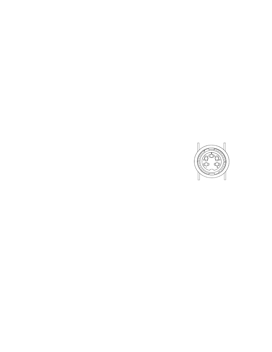
leads from pins 1 and 2 of the receptacle to pins 1 and 2 of the tool plug.
Attach resistors and lamp to .057 dia. pins (do not use long wire). A
WC1000 calibration reference unit is available as an alternative.
CAUTION:
Momentary contact with receptacle pins other than those indicated may damage the electronic
components. To prevent this, turn unit off when removing or inserting resistors or indicators. Momen-
tary shorts when connecting to test points will cause permanent damage to circuit components. If the
soldering tool is used as the load, then the power unit should not be turned above 400°F (205°C) for
more than 1 minute to prevent damaging the heating element.
DEC1001 CALIBRATION CHECK
1. Disconnect soldering tool plug and insert resistor B in socket pins 3 and 4 and indicator lamp and load in pins 1
and 2; or use WC1000 Calibration Reference Unit.
2. Rotate temperature set knob fully CCW and turn unit on. Indicator lamp should be out. Allow 30 minute warmup
before continuing.
3. Rotate temperature set knob fully CW, indicator lamp should be on. Rotate temperature set knob CCW until
indicator lamp stops flashing. Temperature set should = 730°F ±10° (390°C ±6°).
4. Replace resistor B with resistor A. Rotate temperature set knob CCW until indicator lamp stops flashing. Tempera-
ture set should = 375°F ±10° (190°C ±6°).
NOTE: If unit does not pass above checks, refer to troubleshooting guide.