2 valco electric actuators – VICI DVSP User Manual
Page 7
2.2 Valco Electric Actuators
Multiposition actuators require only one event to step the valve/actuator to its next
position. However, the two position actuator requires two intervals: one to switch
the two position valve to its inject position and another to switch it to its load
position.
2.21
Multiposition
The steps below are illustrated in Figure 5.
1.
Locate the two pairs of adjacent grey and
white wires in the interface cable supplied with
the actuator. The relevant pair for this applica-
tion is the one near the center of the ribbon
cable.
2.
Connect the grey (STEP) wire to the NO
terminal of the appropriate relay.
3.
Connect the white (GRND) wire to C or the
same relay.
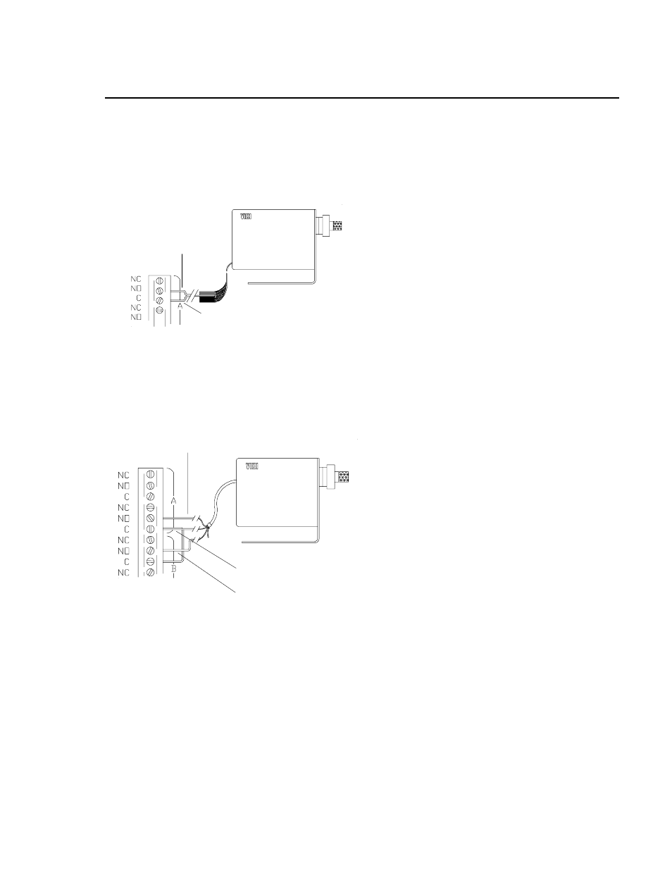
2.22
Two position
The steps below are illustrated in Figure 6.
1. Locate the black, red, and green wires in the
remote switching cable extending from the
cover of the actuator.
2. Connect the black (INJECT) wire to the NO
terminal of the appropriate relay for the de-
sired interval.
3. Connect the red (LOAD) wire to the NO
terminal of the relay corresponding to the
interval where sample is to be loaded.
4. Connect the green (GRND) wire to the
Common of one of the relays and use a
jumper to connect it to the Common of the
other relay.
GREY WIRE
Figure 5:
Valco multiposition electric actuator
GREEN WIRE
BLACK WIRE
RED WIRE
WHITE WIRE
Figure 6:
Valco two position electric actuator
5