Implementation – VICI DVSP User Manual
Page 4
2.
IMPLEMENTATION
Before removing the top cover of the DVSP, make certain that the power
cord is unplugged.
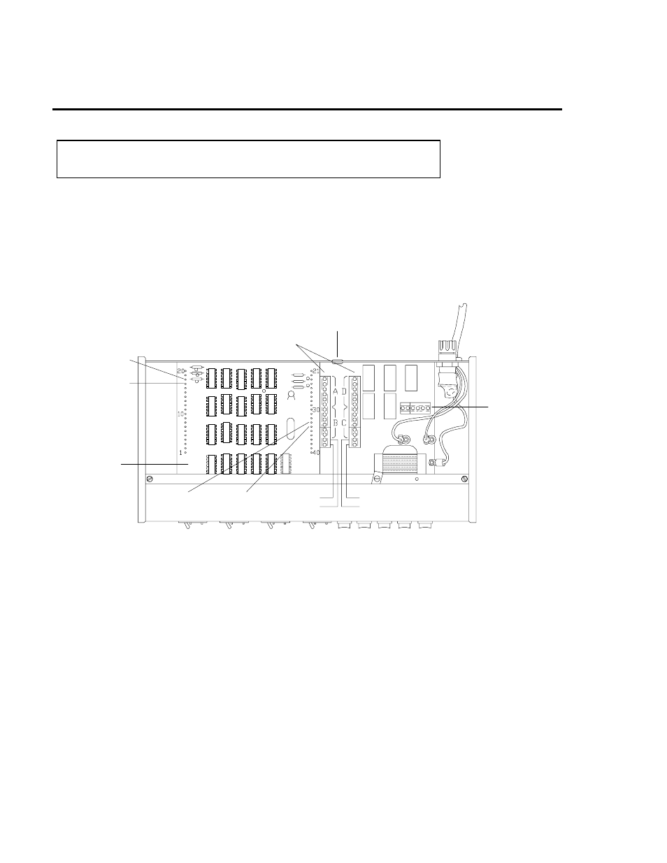
Remove the two screws on the upper rear panel which secure the top cover. Look
at Figure 1 to locate the two barrier terminal strips located near the center of the
large printed circuit board. The terminals are grouped beside letters denoting re-
lays A, B, C, and D, and are marked C for Common, NO for Normally Open, and
NC for Normally Closed. For convenience, the power line (fused and switched) is
connected to two of the terminals on the DVSP mother board, labelled HOT and
NEUT. HOT is the high side of the line and NEUT is the low side.
For operation of devices requiring line voltage (1 amp max), one side of the device
is connected directly to the NEUT terminal and the HOT is switched by the output
relays. For devices which operate on 12 VDC (300 mA max), voltage can be
supplied to any of the relays with a simple jumper connection between the terminal
marked 12 and the Common terminal of the target relay. (Figure 2) Any external
power source can be connected to a Common in the same manner, with a hole
provided in the rear panel to allow a passage for all the external wiring.
The DVSP output relays are double pole, double throw (DPDT), meaning that they
have two separate sets of contacts with no connection from one set to the other.
One contact of each set is the common (C), which is connected to the normally
closed (NC) contact when the DVSP is
not
in the interval corresponding to that
relay. As the DVSP enters each interval, the corresponding relay switches and
connects the common (C) terminal to the normally open (NO) terminal, sending
the current to the external device.
TERMINAL STRIPS
HOT
NEUT
TERMINALS FOR
ADDITIONAL RELAY WITH
TWO SECOND CONTACT
GRND
+12
HOLE FOR WIRING
LOGIC
BOARD
PIN FOR RE-
MOTE "RUN"
PIN FOR
REMOTE "STOP"
PIN FOR
REMOTE
"GROUND"
PIN FOR
REMOTE
"+12"
Figure 1: View of DVSP with cover removed
2