Trebor PC7 User Manual
Page 13
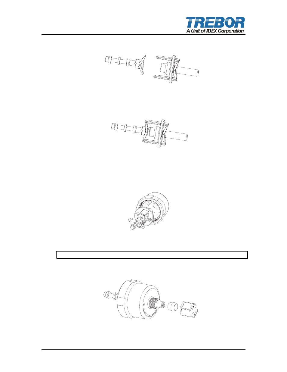
• Lastly insert 2 ea. detent legs into slots on shuttle spool as shown in Figure 3
and insert into previous assembly.
MTD0632
Figure 3
• See completed detent assembly illustrated in Figure 4.
M D 63
T 0 3
Figure 4
• Insert detent assembly into adjustable cap as shown here and install 2 each
retaining screws.
MTD0634
Figure 5
Note: Do not over tighten screws. Cap threads are easily stripped.
• Install ferrule onto adjustment screw with the longest taper toward the
adjustment cap. Then install compression nut onto cap per figure 6.
MTD0 3
6 5
Figure 6
PC7 CONTROLLER OPERATION / MAINTENANCE MANUAL
PAGE 13