tekmar 444 Mixing Expansion Module User Manual
Page 2
© 2007
D 444 - 04/07
2 of 4
Table of Contents
Sequence of Operation ...................................................2
System Pump Operation ................................................3
DIP Switch Settings ........................................................3
LED Status Indicators .....................................................3
Cleaning the Module ......................................................4
Error Messages ..............................................................4
Warranty .........................................................................4
The tN4 System Control determines the required mix
supply water temperature based on its settings and the
requirements of the tN4 thermostats connected to the same
tN4 bus as the 444.
The 444 operates a mixing device to maintain the required
water temperature at its Mix Supply sensor. A mixing device
can include:
•
• Variable speed injection pump.
•
• Floating action actuated mixing valve.
•
• Analog signal actuated mixing valve.
•
• Analog signal to variable frequency drive (VFD) operated
pump.
•
• Analog signal to modulating steam to hot water valve.
Variable Speed Injection
A standard wet rotor circulator can be connected to the
variable speed output on the back of the module. The control
increases or decreases the power output to the circulator
when there is a requirement for mixing. The circulator
speed varies to maintain the correct mixed supply water
temperature at the mix supply sensor. For correct sizing
and piping of the variable speed injection circulator, refer
to essay E 021.
A visual indication of the current variable speed output is
displayed by the Mix % Out LED bar graph.
Sequence of Operation
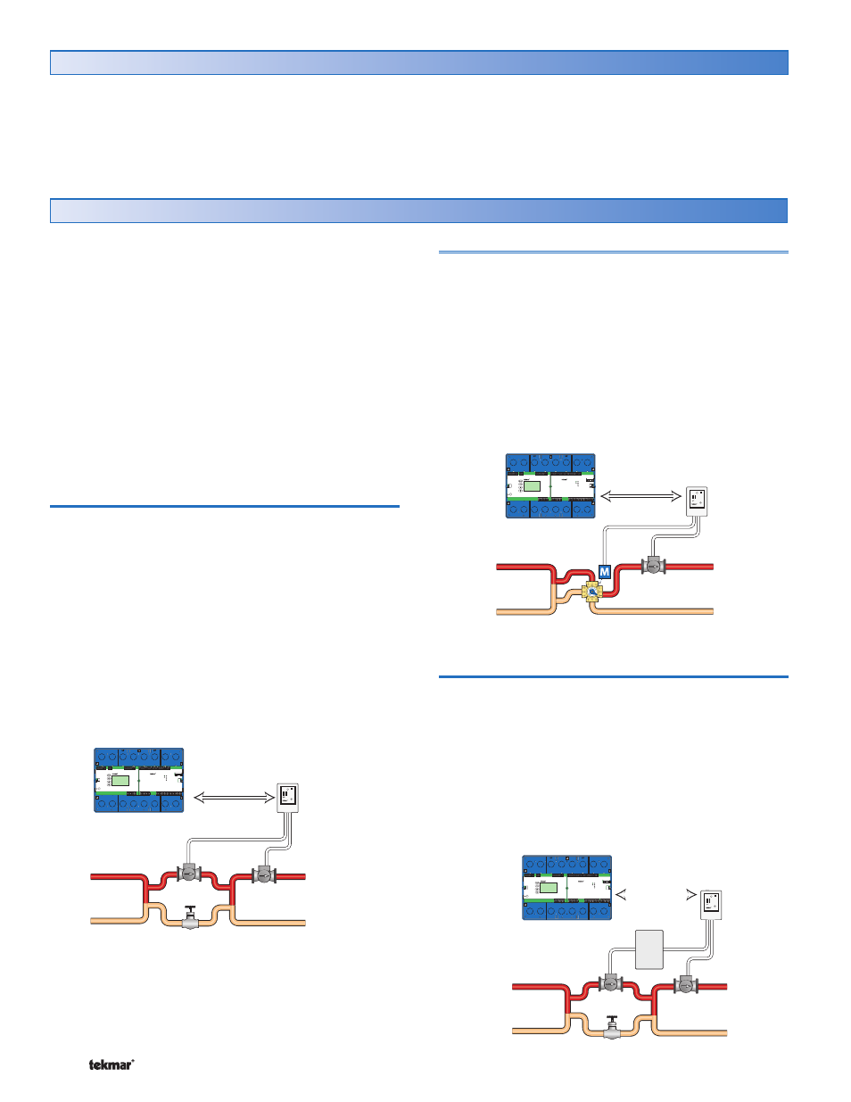
Floating Action
A floating action actuator motor can be connected to the
control on the Opn and Cls terminals. The module pulses
the actuator motor with 24 V (ac) to open or close the valve
in order to maintain the correct supply water temperature
at the mix supply sensor when there is a requirement for
mixing. The mixing valve that the actuator is connected to
can be either a 2-way, 3-way or 4-way valve.
A visual indication of the current variable speed output is
displayed by the Mix % Out LED bar graph.
Test
Reset
Module
Zone
Manager
444
tN4 Mix Bus
Variable Speed
Injection Pump
Mix System
Pump
Test
Reset
Module
Zone
Manager
444
tN4 Mix Bus
Mix System
Pump
Analog Signal
An analog 0-10 V (dc), 2-10 V (dc), 0-20 mA, or 4-20 mA
signal can be provided by the modulating output on the
control. The analog signal can be used to operate a
modulating mixing valve, a modulating steam to hot water
valve, or a variable frequency drive (VFD) which in turn
operates a pump.
A visual indication of the analog output is displayed by the
Mix % Out LED bar graph.
Test
Reset
Module
Zone
Manager
444
VFD
tN4 Mix Bus
Variable Speed
Injection Pump
Mix System
Pump