tekmar 441 Mixing Expansion Module User Manual
Page 2
© 2007
D 441 - 08/07
2 of 4
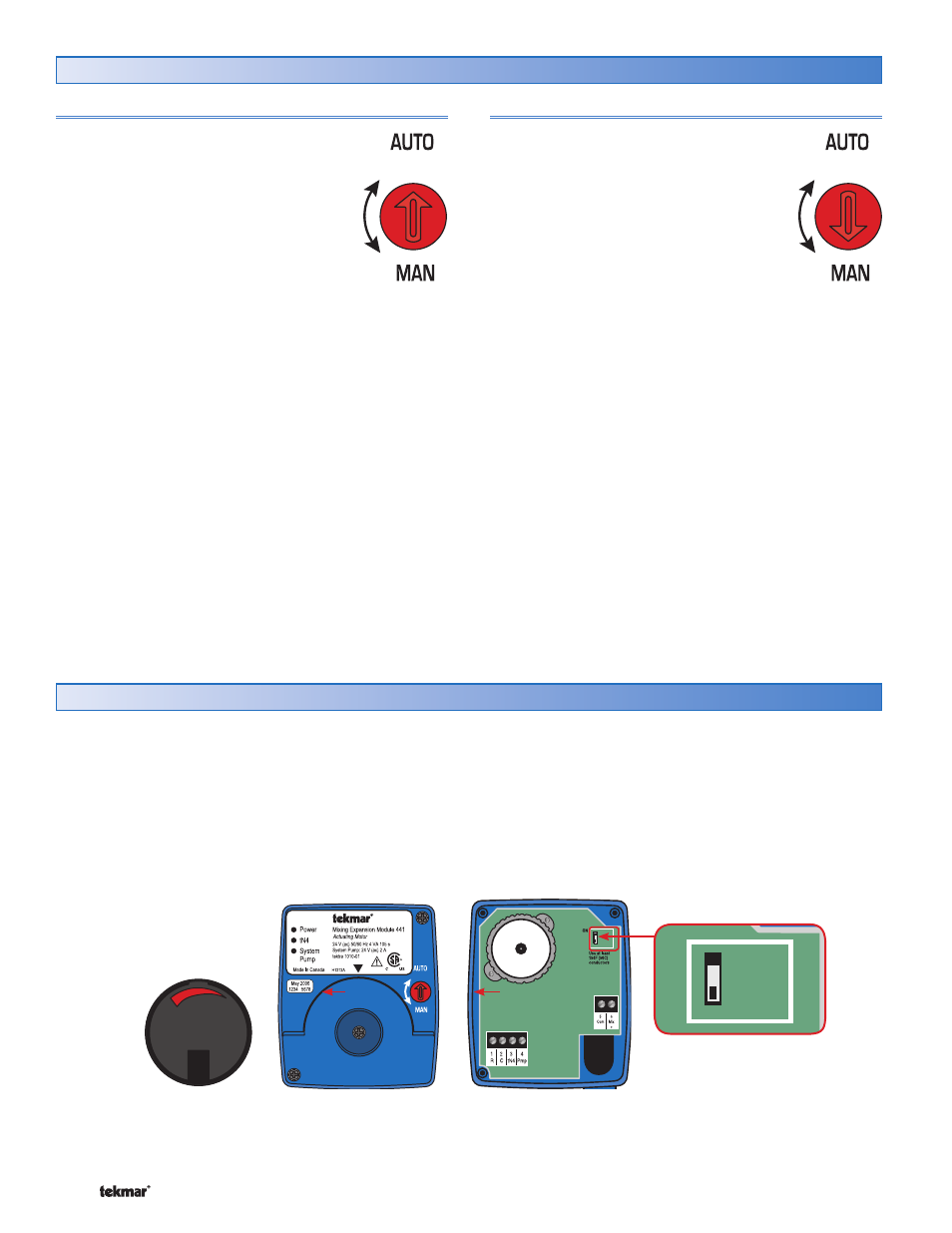
Sequence of Operation
Automatic Operation
Automatic operation of the mixing valve
requires the red dial on the front of the 441
to be set to the “AUTO” position.
The tN4 System Control determines the target
mix supply water temperature based on its
settings and the requirements of the tN4
thermostats and tN4 setpoint devices on the
mix tN4 bus. The 441 uses the Mix Supply
sensor to measure the water temperature and
then operates the mixing valve to maintain the target water
temperature. The 441 powers the system pump output with
24 V (ac) whenever a tN4 thermostat or tN4 setpoint control
calls for heat on the tN4 mix bus and that tN4 device’s Heat
1 Pump (or Heat 2 Pump) setting is set to On.
The position of the mixing valve is indicated by the red
stripe on the hand wheel.
Manual Operation
Manual operation of the mixing valve requires
the red dial on the front of the 441 to be set
to the “MAN” position.
To change the mixing position, rotate the hand
wheel of the 441.
The position of the mixing valve is indicated
by the red stripe on the hand wheel.
The 441 has a DIP switch located inside the wiring
enclosure.
Step 1: Remove the hand wheel.
Step 2: Remove the two screws.
Step 3: Remove the front cover.
DIP Switch Setting
The DIP switch selects the direction of rotation to open
the mixing valve.
In the OFF position, the actuator moves in the clockwise
direction to open the valve.
In the ON position, the actuator moves in the counterclockwise
direction to open the valve.
ON
ON