Dip switch settings sequence of operation, Variable speed injection, Floating action – tekmar 440 Mixing Expansion Module User Manual
Page 2: System pump operation
© 2005
D 440 - 06/05
2 of 4
DIP Switch Settings
Sequence of Operation
51
52
54
55
C
Com Mix
R
R
Opn
53
Cls
N
N
Variable Speed
System
56
57
58
59
Pump
Pump
tN4
Variable / Floating
Powered Output
Floating Output:
24 V (ac) 8 VA
Meets Class B: Canadian
ICES & FCC Part 15
Made in Canada
Var. Pump Fuse
T2.5 A 250 V
7.5 A (max)
2.5 A
Mixing Expansion Module 440
tektra 1000-02
Var. Pump: 115 V (ac) 2.5 A
Relay Rating: 115 V (ac) 5 A
Power
System Pump
Mix % Out
Open
Close
No power
H7009B
Variable / Floating
The tN4 System Control determines the required mix
supply water temperature based on its settings and the
requirements of the tN4 thermostats connected to the same
tN4 bus as the 440.
The 440 operates either a variable speed injection pump
or a floating action mixing valve to maintain the required
water temperature at its Mix Supply sensor.
Variable Speed Injection
A standard wet rotor circulator can be connected to the
Variable Speed output on the control. The control increases
or decreases the power output to the circulator when there
is a requirement for mixing. The circulator speed varies to
maintain the correct mixed supply water temperature at
the mix supply sensor. For correct sizing and piping of the
variable speed injection circulator, refer to essay E 021.
A visual indication of the current variable speed output is
displayed by the Mix % Out LED.
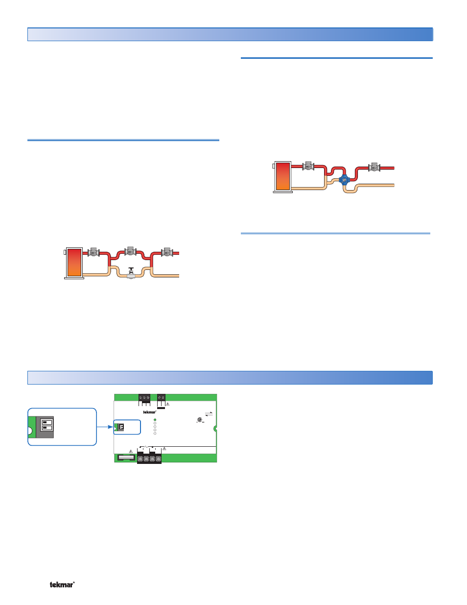
Floating Action
A floating action actuator motor can be connected to the
control on the Opn and Cls terminals. The control pulses
the actuator motor open or close to maintain the correct
supply water temperature at the mix supply sensor when
there is a requirement for mixing. The mixing valve that the
actuator is connected to can be either a 2-way, 3-way or
4-way valve. A visual indication as to whether the control is
currently opening or closing the mixing valve is displayed
by the Open and Close LEDs.
System Pump Operation
The System Pump contact operates based on the settings
of the tN4 thermostats connected to the same tN4 bus
as the 440.
The DIP switches are found on the left hand side of the 440.
Variable
•
• The 440 uses the Variable Speed output to control a
variable speed injection pump.
Floating
•
• The 440 uses the Floating Action output to control a
24 V (ac) floating action actuator.