Rite-Ride 4174 User Manual
Page 2
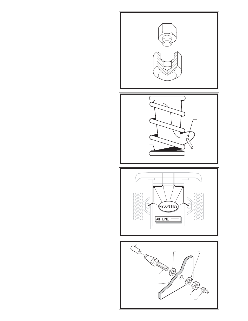
FIGURE "D"
FIGURE "E"
FIGURE "F"
AIR
INLET
LOWER
PROTECTOR
AIR LINE
PUSH-TO-CONNECT
INFLATION VALVE
FLAT WASHER
HEX NUT
VALVE CAP
BODY OF
VEHICLE
S
TEP
5 - A
DJUST
THE
AIR
SPRING
Push the air spring up into the coil spring by hand or
with a blunt tool, such as a socket extension. DO NOT use
any thing with sharp edges or corners, as this may damage
the air spring.
When the air spring is completely within the coil spring,
remove the plug and tubing section by pushing the collar
on the fitting towards the air spring and pulling out the
tubing. Allow the air spring to return to its normal shape.
Push the air spring to the top of the coil spring and
orient the air spring so that the push-to-connect air fitting
on the air spring is visible through the hole in the retainer
plate.
S
TEP
6 - R
OUTE
THE
AIR
LINE
Cut the air line tubing into two equal lengths, making
sure the tubing is cut as squarely as possible (a "saw" cut
with a sharp knife is preferred). Select a location on the
vehicle for the inflation valves. This location can be on the
bumper or body of the vehicle, as long as it is in a protected
area. (Note: The inflation valve will be installed in Step 7).
Insert the air line tubing into the push-to-connect fitting
on the air spring as far as possible. Route the air line from
the air spring to the desired inflation valve location.
With the tubing routed from the air spring to the
inflation valve location, use the nylon ties supplied to
secure the air line tubing to the vehicle see Figure "E".
Route the tubing to avoid heat and sharp edges when
fastening the tubing to the vehicle. Route the tubing away
from the exhaust system. A heat shield and installation
manual have been provided to protect the air spring from
exhaust heat.
S
TEP
7 - I
NSTALL
THE
INFLATION
VALVE
Drill a 5/16" hole where you wish to mount the inflation
valve. Remember to keep the inflation valve in a protected
area that is easily accessible. Attach the inflation valve to
the bumper or body of the vehicle see Figure "F".
Cut the excess air line tubing so that it will fit easily into
the inflation valve, making sure the end is cut squarely (a
"saw" cut with a sharp knife is preferred). Push the end
of the tubing into the inflation valve as far as possible.
S
TEP
8 - I
NSTALL
THE
OPPOSITE
-
SIDE
AIR
SPRING
Follow steps 2-7 to install the second air spring on the
remaining side of the vehicle.
S
TEP
9 - I
NFLATE
AND
TEST
Inflate the air springs to recommended maximum
operating pressure (see page 1 for operating pressures).
With a soap and water solution, check for air leaks around
the fittings and valve core. We recommend inflating and
deflating in 5 p.s.i. increments to find the ideal riding
condition for your vehicle.
This now completes the installation. Raise the vehicle
and remove the jack stands and lower the vehicle to the
ground. Re-attach the positive battery cable.
UPPER SUPPORT
FIGURE "C"