Coil-rite installation procedure – Rite-Ride 4173 User Manual
Page 3
COIL-RITE INSTALLATION PROCEDURE
NOTE: CHECK AIR PRESSURE
ON A MONTHLY BASIS.
Figure “D”
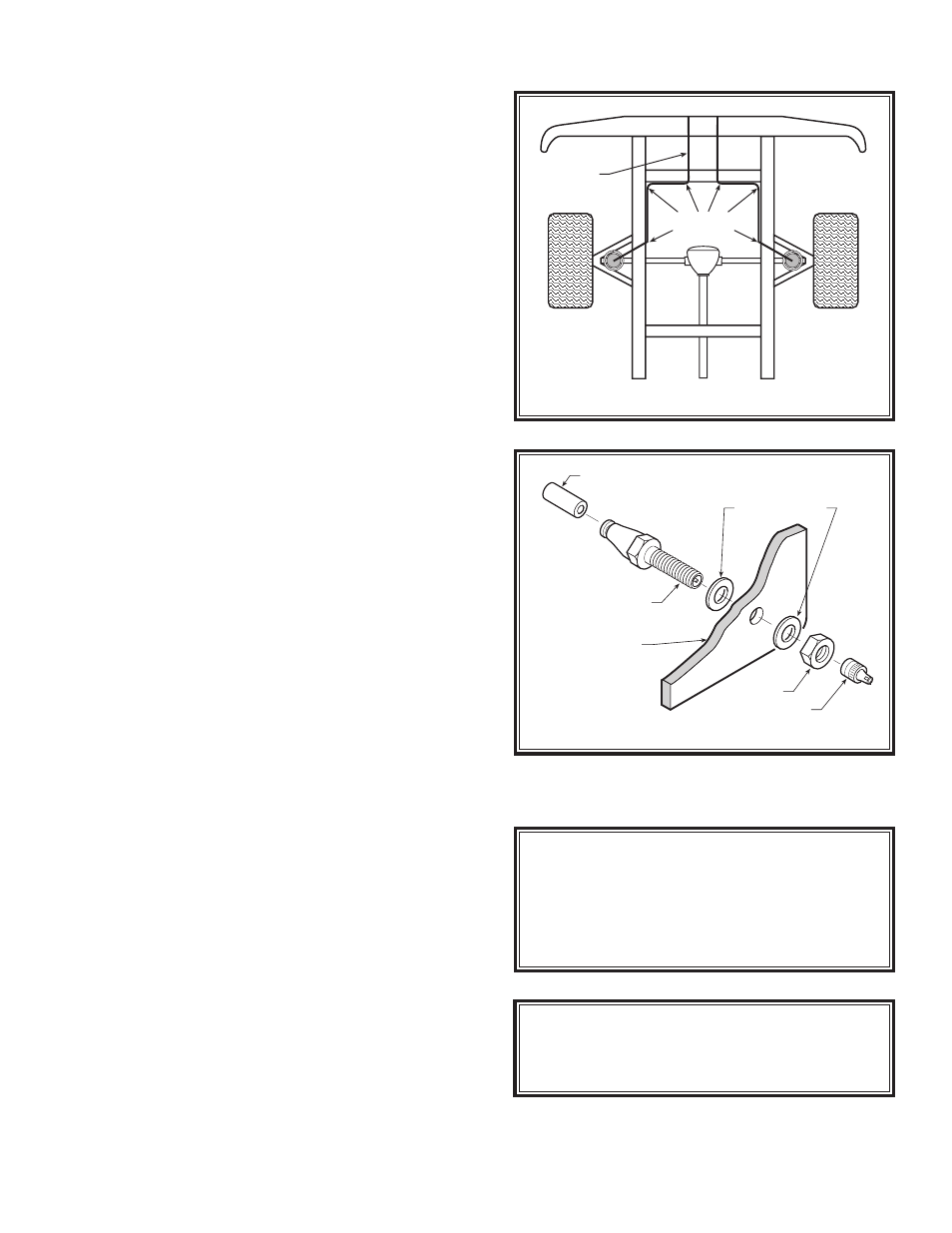
Figure “E”
STEP 6—INSTALL THE INFLATION VALVE
Drill a 5/16" hole where you wish to mount the inflation
valve. Remember to keep the inflation valve in a protected
area that is easily accessible. Attach the inflation valve
to the bumper or body of the vehicle,
see Figure “E”.
Cut the excess air line tubing so that it will fit easily
into the inflation valve, making sure the end is cut squarely
(a “saw” cut with a sharp knife is preferred). Push the end
of the tubing into the inflation valve as far as possible.
STEP 7—INSTALL THE OPPOSITE-SIDE AIR
SPRING
Follow Steps 2-6 to install the second air spring on the
remaining side of the vehicle. Note: Raise the axle by the
differential approximately 2" and remove the jack stand
under the axle on the passenger side and place under
the drivers side of the vehicle. Lower the jack and allow
the suspension to hang freely for installation on the pas-
senger's side. Be sure not to over extend the brake line.
STEP 8—COMPLETION
This now completes the installation. Jack the vehicle up
approximately 2" under the differential and remove the
jack stand from under the axle. Reattach the panhard rod,
emergency brake cable clip, sway bar links, and shocks.
Inflate the air springs to 10–15 psi. Torque fasteners
to manufacturers specifications. Raise the vehicle and
remove the jack stands from under the frame and lower
the vehicle to the ground. Re-attach the negative battery
cable. Remove the wheel chocks from the front wheels.
STEP 9—INFLATE AND TEST
Check the recommended inflation pressure and inflate the
air springs to recommended maximum operating pres-
sure (see Page 1 for operating pressures). With a soap
and water solution, check for air leaks around the fittings
and valve core. We recommend inflating and deflating in
5 p.s.i. increments to find the ideal riding condition for
your vehicle.
NYLON
TIES
AIR LINE
AIR LINE
PUSH-TO-CONNECT
INFLATION VALVE
FLAT WASHER
HEX NUT
VALVE CAP
BODY OF
VEHICLE
FOR BEST RIDE use only enough air
pressure in the air helper springs to level the
vehicle when viewed from the side (front to
rear). This amount will vary depending on the
load, location of load, condition of existing
suspension and personal preference.
NOTE:
MIN PRESSURE
5 PSI
MAX PRESSURE (LOADED)
35 PSI