Coil-rite installation procedure – Rite-Ride 4173 User Manual
Page 2
REMOVE
REMOVE
REMOVE BURRS FROM
CUT EDGES
OVERLOAD BUMPER
remove the emergency brake cable clip located on the
rear center of the axle allowing the emergency brake line
to hang freely,
see Figure “A”. The panhard rod must be
unbolted on the drivers side rear of the axle in order to
lower the suspension to free the coil springs,
see Figure
“A”. To remove the coil springs place a jack stand under
the passenger side axle (leave the current jack stands
under the frame in place) as close to the wheel as pos-
sible. Then lower the jack under the differential allowing
the drivers side suspension to hang freely. Take special
precautions not to overextend the the flexible hydraulic
barke line,
see Figure “A”. Remove the driver's side coil
spring and rubber overload bumper.
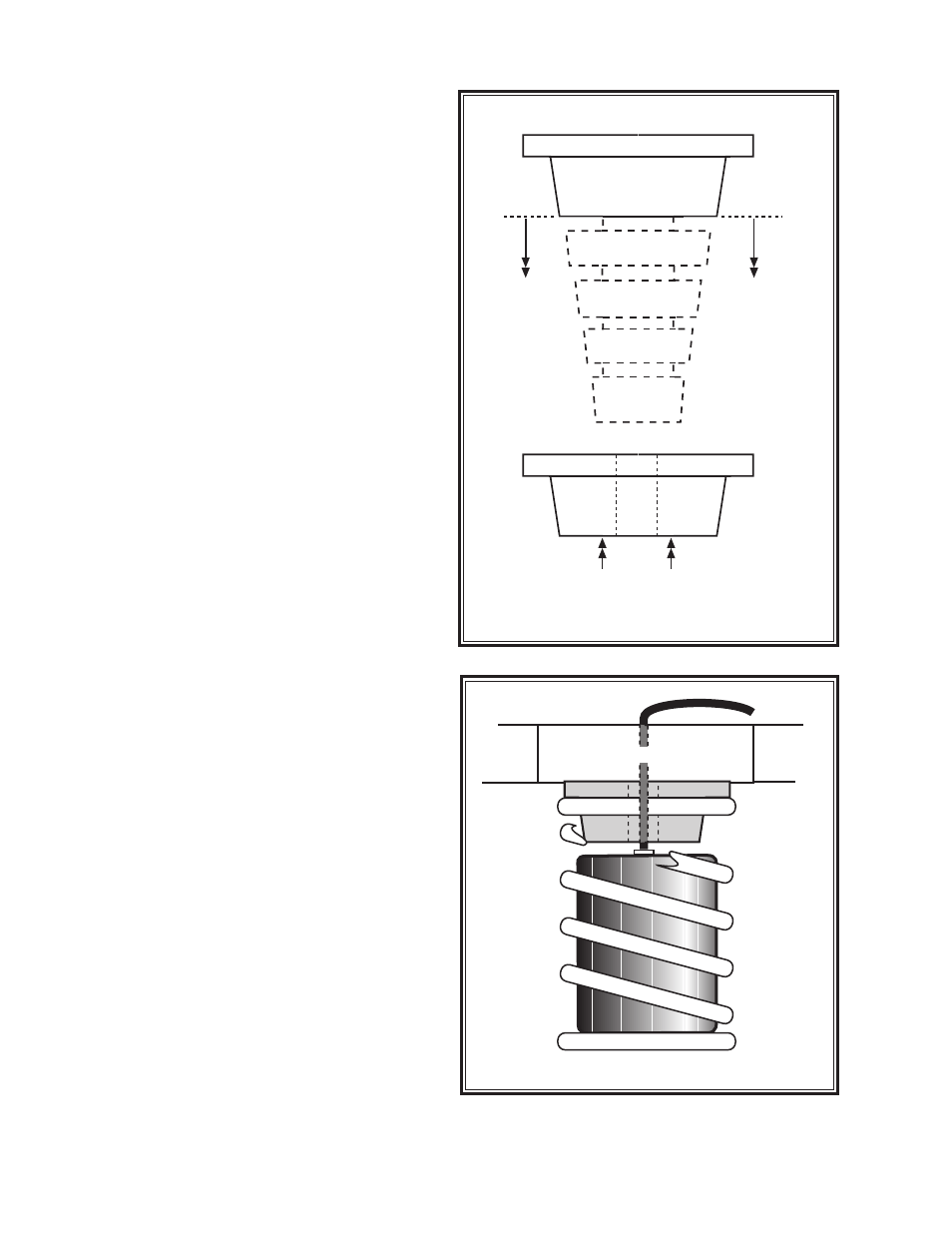
STEP 2—OVERLOAD BUMPER
PREPARATION
To provide enough operating distance for the air helper
spring the existing overload bumper must be modified.
After removal of the overload bumper the four (4) con-
voluted sections of the bumper should be cut off. This
is accomplished by holding the largest portion of the
bumper in a vice and using a hack saw to remove the
upper portion of the overload bumper see Figure "B". As
a helpful hint use glass cleaner to lubricate the saw blade
for easier cutting. The lower convoluted portion of the
overload bumper will not be used. The upper portion will
be needed to complete this installation,
see Figure “B”.
STEP 3—INSTALL THE AIR SPRING
Insert the air helper spring into the driver's side coil spring
with the air inlet towards the top of the coil spring,
see
Figure “C”. Cut the air line tubing into two equal lengths,
making sure the tubing is cut as squarely as possible
(a “saw” cut with a sharp knife is preferred). Insert the
air line tubing into the push-to-connect fitting on the air
spring as far as possible.
STEP 4—RE-INSTALL THE OVERLOAD
BUMPER
After the air spring has been installed into the coil spring
place the converted overload bumper back in its original
position on top of the coil spring with the air line routed
through the hole in the center,
see Figure “C”. The top
of the air spring will be next to the bottom of the overload
bumper. The coil spring will be re-installed after the air
line has been inserted through the upper spring seat
and installed in the air spring refer to the following step.
Make sure that the bottom of the spring is seated in the
spring retainer properly. Route the air line tubing through
the top of the upper spring seat and through the hole in
the overload bumper,
see Figure “C”
STEP 5—ROUTE THE AIR LINE
Route the air line from the air spring to the desired infla-
tion valve location. Do not fold or kink the air line tubing.
With the tubing routed from the air spring to the
inflation valve location, use the Nylon ties supplied to
secure the air line tubing to the vehicle,
see Figure “D”.
Be careful to avoid heat and sharp edges when fastening
the tubing to the vehicle. Route the tubing away from the
exhaust system.
COIL-RITE INSTALLATION PROCEDURE
Figure “B”
Figure “C”
UPPER SPRING SEAT