Step 1 — prepare the vehicle, Step 2— pre-assemble the kit, Step 3 - install the assembly to the vehicle – Rite-Ride 2485 User Manual
Page 3: Step 4 — install the driver’s side assembly, Step 5 — install the air line and inflation valve, Step 6 — check the air system
STEP 1 — PREPARE THE VEHICLE
This installation assumes that there is no load in the vehicle.
With the vehicle on a solid, level surface chock the front wheels.
Raise the vehicle by the rear axle and remove the rear wheels. After
the removal of the wheels lower the vehicle so the axle rests on jack
stands rated for your vehicles weight. Remove the negative battery
cable. Remove the jounce bumpers located under the frame rail by
pulling them down at an angle until it pulls off the jounce bumper stud.
The jounce bumpers will not be re-used with this kit.
STEP 2— PRE-ASSEMBLE THE KIT
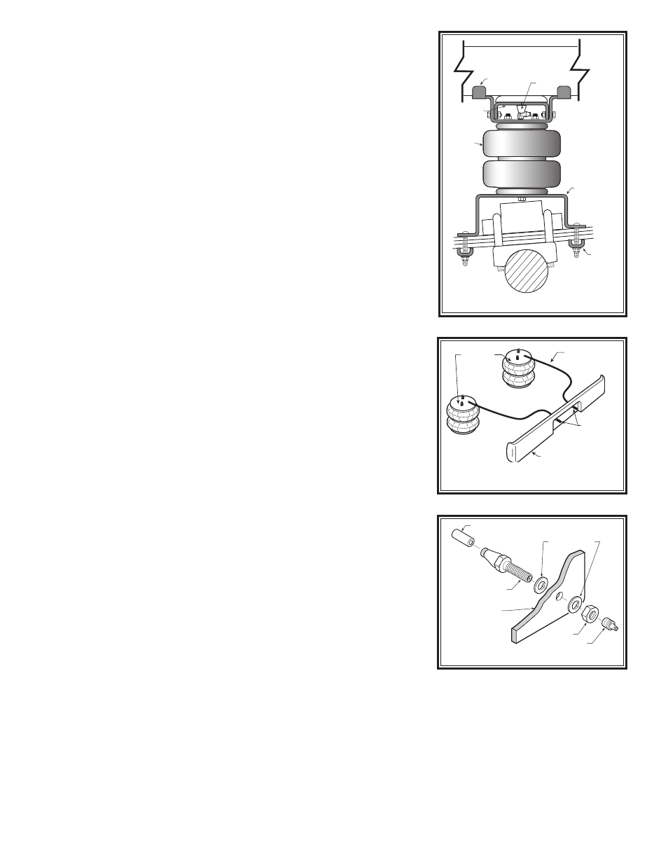
Select one air spring and one upper bracket from the kit. Insert studs
of the airspring into the two small outer holes in the upper bracket.
Make sure the air inlet is visible through the large hole. Fasten the air
spring to the upper bracket using two 3/8"-16 flange lock nuts. See Fig-
ure “A”. Install the elbow fitting into the air inlet on the air spring and
tighten it enough to engage the orange thread sealant. Point the elbow
fitting towards the location of the inflation valves. See Figure “C”.
Next, attach a lower bracket to the air spring using a 3/8"-16 x 3/4"
flanged bolt. See Figure “A”.
STEP 3 - INSTALL THE ASSEMBLY TO THE VEHICLE
Place two of the “L” brackets onto the frame, around the jounce bum-
per stud. See Figures “A” & “B”. Place the air spring assembly over
the "L" brackets and onto the frame. Attach the upper bracket to the
“L” brackets using four 5/16"-24 X 3/4" bolts and 5/16" flange lock nuts.
See Figure “A”.
Align the lower bracket on top of the leaf spring so the short leg of
the lower bracket is forward of the axle. Insert four carriage bolts into
the square holes in the bracket bracket as shown in Figures “A” &
“B”. Place the bracket clamps over the carriage bolts and secure with
the 3/8"-16 flange lock nuts, see Figures “A” & “B”.
Important: In order for the air spring to function properly, there
must be a minimum of 1/2" of clearance around the air spring.
STEP 4 — INSTALL THE DRIVER’S SIDE ASSEMBLY
Follow steps 1-3 for assembly and installation of the driver's side.
STEP 5 — INSTALL THE AIR LINE AND INFLATION VALVE
Uncoil the air tubing and cut it in two equal lengths. DO NOT FOLD OR
KINK THE TUBING. Make the cut as square as possible. Insert one
end of the tubing into the push-to-connect elbow fitting installed in the
top of the air spring as far as possible.
Select a location on the vehicle for the air inflation valves. The loca-
tion can be on the bumper or the body of the vehicle, as long as it is in
a protected location so the valve will not be damaged, but still maintain
accessibility for the air chuck, see Figure “C”. Drill a 5/16" hole and
install the air inflation valve using two 5/16" flat washers per valve as
supports, see Figure “D”. Run the tubing from the air helper spring to
the valve, routing it to avoid direct heat from the engine, exhaust pipe,
and away from sharp edges. Thermal sleeves have been provided
for these conditions. The air line tubing should not be bent or curved
sharply as it may buckle. Secure the tubing in place with the Nylon ties
provided. Push the end of the air line tubing into the inflation valve, see
Figure “D”.
STEP 6 — CHECK THE AIR SYSTEM
Once the inflation valves are installed, inflate the air helper springs to
70 psi and check the fittings for air leaks. Using a spray bottle, apply
a solution of soap and water to the fittings. If a leak is detected at a
airline tubing connection then check to make sure that the airline tube
is cut as square as possible and that it is pushed completely into the
fitting. The airline tubing can easily be removed from the fittings by
exhausting all the pressure in the air springs and then pushing the col-
FRAME
FRONT
REAR
UPPER
BRACKET
“L” BRACKETS
AIR
SPRING
JOUNCE
BUMPER
STUD
AXLE
PAD
LOWER
BRACKET
BRACKET
CLAMP
FIGURE “B”
AIR HOSE
INFLATION
VALVES
BUMPER
AIR
SPRINGS
AIR LINE
PUSH-TO-CONNECT
INFLATION VALVE
FLAT WASHER
HEX NUT
VALVE CAP
BODY OF
VEHICLE
FIGURE “D”
FIGURE “C”