Step 1—prepare the vehicle, Step 2—pre-assemble the kit, Step 3—installing the assembly to the vehicle – Rite-Ride 2551 User Manual
Page 3: Step 5—air tubing installation, Step 6—check the air system
STEP 1—PREPARE THE VEHICLE
With the vehicle on a solid, level surface chock the front wheels.
Remove the negative battery cable. Raise the vehicle by the axle and
remove the rear wheels. After the removal of the wheels lower the vehi-
cle so the axle rests on jack stands rated for vehicles weight. Remove
the jounce bumpers located under the frame rail. The jounce bumpers
will not be re-used with this kit; the bolts will be re-used in Step 3.
STEP 2—PRE-ASSEMBLE THE KIT
Install the upper bracket by inserting the air helper spring combo-stud
into the hole, use the 5/8"-18 Nylon lock nut to secure the bracket to the
air spring, see Figure “A”. Install the air fitting as shown in Figure “A”.
Tighten the air fitting securely to engage the orange thread sealant.
Fasten the lower bracket to the air helper spring using a 3/8"-16 x 3/4"
hex bolt, see Figure “A”.
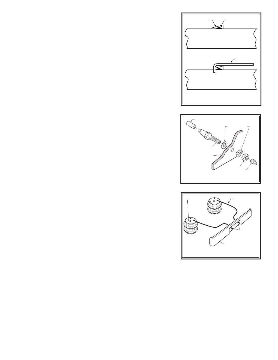
STEP 3—INSTALLING THE ASSEMBLY TO THE VEHICLE
PLEASE NOTE: On the left side of the axle there is a small bracket
that will need to be trimmed so the lower bracket will rest firmly on
the axle, please see Figure “B”. Trim the bracket back to where it is
welded onto the axle or about 1/4" of an inch.
Place the assembly on the driver’s side on top of the axle housing; see
Figures “A” and “B”. Install the upper bracket onto the vehicle using
jounce bumper bolts previously taken out into the threaded holes from
the jounce bumper. Attach the lower bracket to the axle using four 3/8"-
16 x 3-1/2" carriage bolts and 3/8"-16 flange lock nuts, see Figure “A”.
Once the assembly is in place, you must have a minimum of 1/2" clear-
ance around the air spring for proper operation.
STEP 4—INSTALLATION TO THE PASSENGER’S
SIDE ASSEMBLY
Reverse any orientations when assembling and installing the right, or
passenger’s side of the vehicle.
STEP 5—AIR TUBING INSTALLATION
Uncoil the air line and cut it into two equal lengths. DO NOT FOLD OR
KINK THE TUBING. Try to make the cut as square as possible. Insert
one end of the air line into the elbow fitting installed in the top of the air
helper spring. Push the tubing into the fitting as far as possible.
Select a location on the vehicle for the air inflation valves. The loca-
tion can be on the bumper or the body of the vehicle, as long as it is in a
protected location so the valve will not be damaged, but maintain acces-
sibility for the air chuck, see Figure “D”. Drill a 5/16" hole and install
the air inflation valve using two 5/16" flat washers per valve as sup-
ports; see Figure “C”. Run the air line from the air helper spring to the
valve, routing it to avoid direct heat from the engine, exhaust pipe, and
away from sharp edges. Thermal sleeves have been provided for these
conditions. The air line tubing should not be bent or curved sharply as
it may buckle. Secure the air line in place with the nylon ties provided.
Push the end of the air line into the inflation valve as illustrated; see
Figure “C”.
STEP 6—CHECK THE AIR SYSTEM
Once the inflation valves are installed inflate the air helper springs to
70
psi and check the fittings for air leaks with an applied solution of soap
and water. If a leak is detected at an air line connection then check to
make sure that the air line is cut as square as possible and that it is
pushed completely into the fitting. The tubing can easily be removed
from the fittings by pushing the collar toward the body of the fitting and
then pulling out the tube. If a leak is detected where the brass elbow fit-
ting screws into the spring, remove the air line, then screw the elbow fit-
ting into the spring one additional turn or until the leak stops. Reinstall the
air line and re-inflate the air springs and check for leaks as noted above.
This now completes the installation. Install the wheels and torque
the lug nuts to the manufacturer’’ specification. Raise the vehicle by the
FIGURE “B”
FIGURE “C”
AXLE
CUT
LINE
WELD
AXLE
BEFORE
AFTER
LOWER BRACKET
AIR LINE
PUSH-TO-CONNECT
INFLATION VALVE
FLAT WASHER
HEX NUT
VALVE CAP
BODY OF
VEHICLE
FIGURE “D”
AIR HOSE
INFLATION
VALVES
BUMPER
AIR
SPRINGS