Rite-Ride 2551 User Manual
Warning, This kit does not require drilling into the frame
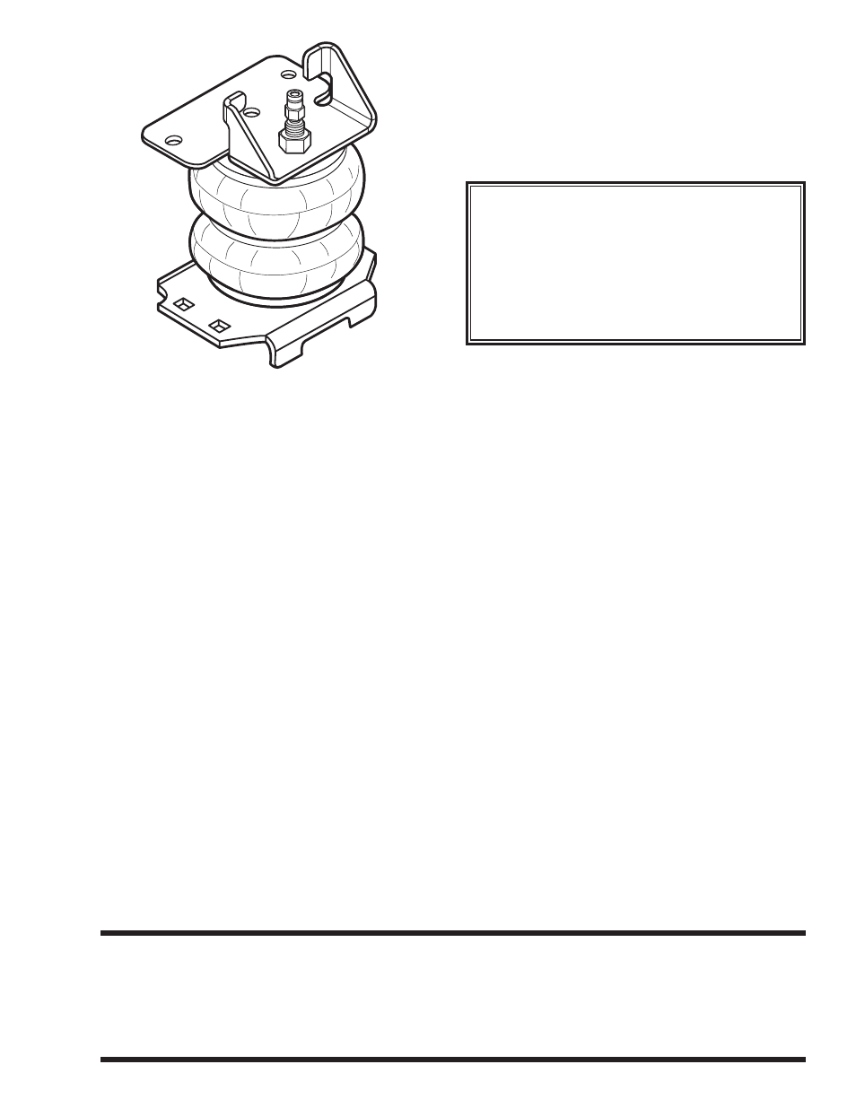
2551
PARTS LIST
INSTALLATION INSTRUCTIONS
Congratulations — your new Air Helper Springs are
quality products capable of improving the handling and
comfort of your vehicle. As with all products, proper
installation is the key to obtaining all of the benefits your
kit is capable of delivering
. Please take a few minutes
to read through the instructions to identify the com-
ponents and learn where and how they are used. It
is a good idea to start by comparing the parts in your kit
with the parts list below.
The heart of the air spring kit is of course, the air
helper springs. Remember that the air helper springs
must flex and expand during operation, so be sure that
there is enough clearance to do so without rubbing
against any other part of the vehicle.
Be sure to take all applicable safety precautions
during the installation of the kit. The instructions listed
in this brochure and the illustrations all show the left,
or diver’s side of the vehicle. To install the right side
assembly simple follow the same procedures.
Your kit includes separate inflation valves and air
lines for each air helper spring. This will allow you to
level your vehicle from side to side as well as from front
to back. If you would rather have a single valve inflation
system, your dealer can supply the optional “T” fitting.
IMPORTANT!
For your safety and to prevent possible damage to
your vehicle, do not exceed the maximum load rec-
ommended by the vehicle manufacturer (GVWR).
Although your Air Helper Springs are rated at a maxi-
mum inflation pressure of 100 psi this pressure may
allow you to carry too great of a load on some vehicles.
Check your vehicle owner’s manual or door decal for
maximum loads listed for your vehicle.
When inflating your Air Helper Springs, add air pres-
sure in small quantities, checking pressure frequently
during inflation. The air spring requires much less air
volume than a tire and, therefore, inflates much quicker.
NOTE:
Please read through this manual completely before
installing the air spring kit to your vehicle. A heat
shield will be required on the exhaust side of the
vehicle.
WARNING:
Do not inflate this assembly when it is
unrestricted. The assembly must be restricted
by the suspension or other adequate
structure. Do not inflate beyond 100 psi.
Improper use or over inflation may cause
property damage or severe personal injury.
AIR SPRING
6766
2
LEFT UPPER BRACKET
5754
1
RIGHT UPPER BRACKET
5755
1
LOWER BRACKET
5756
2
AXLE CLAMP
0530
4
18 FT. TUBING
1
5/16” WASHERS
4
3/8”-16 X ¾” HEX HEAD BOLT
2
04-12
3/8”-16 X 3-1/2” CARRIAGE BOLT
8
3/8”-16 FLANGE HEAD NUT
8
5/8”-18 NYLON LOCK NUT
2
1/8 NPT STRAIGT FITTING
2
INFLATION VALVE
2
THERMAL SLEEVE
2
NYLON TIE WRAP
6
CAUTON TAG
2
THIS KIT DOES NOT REQUIRE
DRILLING INTO THE FRAME.