Rite-Ride 2312 User Manual
Page 3
NOTE:
Please read thorough this manual completely before
installing the air spring kit to your vehicle.
STEP 1— PREPARE THE VEHICLE
With the vehicle on a solid, level surface chock the front
wheels. Raise the vehicle by the axle and remove the back
wheels. After the removal of the wheels lower the vehicle
so the axle rests on jack stands rated for your vehicles
weight. Remove the negative battery cable.
STEP 2 — PRE-ASSEMBLE THE KIT
Note: The upper frame brackets and the upper air spring
brackets are marked “R” and “L” to indicate right side and
left side.
Select the upper air spring bracket marked “R” and the
upper frame bracket marked “R” from the kit. Assemble
the upper air spring bracket and the upper frame bracket
using four 3/8"-16 x 1" hex head bolts and four 3/8"-16
flange nuts,
as shown in Figure “A”.
STEP 3 — INSTALLING THE ASSEMBLY
TO THE VEHICLE
Remove the shock absorber top bolt and move the top of
the shock absorber out of the way. Place the upper bracket
assembly on the frame rail and around the shock absorber
mount. Place the round shim on the outside of the bracket
on the shock absorber mount. Then place the inner upper
bracket marked “R” on the inside of the frame rail and
around the shock absorber mount. Fasten the inside frame
bracket and outside bracket assembly together with two
5/16"-18 x 1" hex head bolts and 5/16"-16 flange lock
nuts. Place the round shim on the outside of the inner
frame bracket on the shock absorber mount. Reinstall the
shock absorber and tighten the shock absorber bolt back
to manufacture’s specifications. Using the upper brackets
as a template drill one 3/8" hole on the inside of the frame
and a 5/8 hole on the outside of the frame.
Before drill-
ing the hole, make sure electrical, brake, and fuel lines
are cleared from the path of the drill. In order to prevent
any damage to these lines, it is recommended that a piece
of wood be placed between the frame rail and the exist-
ing lines. Install the 3/8"-16 x 3 1/2" hex head bolt, frame
sleeve, large flat washer, and secure with a 3/8"-16 flange
lock nut.
Select one air spring from your kit and install the swivel
elbow push to connect fitting. Tighten the air fitting so as
to make contact with the nylon ring and tighten 1/4 turn to
snug the fitting. No thread sealant is needed. Fasten the
air spring to upper bracket the using the 3/8"-16 x 5/8"
flanged bolts,
see Figure “A”.
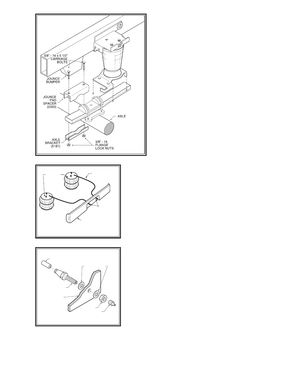
Select one lower bracket from your kit. Insert the 3/8"-
16 x 2 1/2" carriage bolts into the square holes on the
lower bracket. Fasten the air spring to the lower bracket
using the 3/8"-16 x 3/4" flange bolt (finger tight),
see Fig-
ure “A”. Attach the lower bracket to the leaf stack using
the carriage bolts (installed earlier), the flange lock nuts
and bracket strap
as shown in Figure “A”. Tighten up the
3/8"-16 x 3/4" flange bolt in the bottom of the air spring
that was installed earlier. Once the assembly is in place
make sure that you have a minimum of a 1/2" clearance
around the air spring for proper operation.
Figure “D”
AIR LINE
PUSH-TO-CONNECT
INFLATION VALVE
FLAT WASHER
HEX NUT
VALVE CAP
BODY OF
VEHICLE
Figure “C”
AIR HOSE
INFLATION
VALVES
BUMPER
AIR
SPRINGS
Figure “B”