Rite-Ride 2171 User Manual
Page 3
S
TEP
1 - P
REPARE
THE
VEHICLE
With the vehicle on a solid level surface, chock the
front wheels. Raise the vehicle by the axle and remove
the rear wheels. After the removal of the wheels,
lower the vehicle so the axle rests on jack stands rated
for your vehicle's weight. Remove the negative battery
cable.
S
TEP
2 - P
REASSEMBLE
THE
KIT
Preassembly will begin with the right, or passenger's
side of the vehicle. All instructions and illustrations
show the right-side assembly unless otherwise noted.
Select one air helper spring from your kit. Install
the upper bracket by aligning the threaded stud on the
air spring with the large hole on the upper bracket.
Fasten the upper bracket to the air spring using the
supplied 3/4" jam nut and 3/4" star washer see Figure
"A". Install the barbed air fitting into the top of the air
spring. Tighten the air fitting sufficiently to engage at least two threads
with the pre-applied thread sealant. Orient the fitting so that is points
toward the anticipated location of the inflation valve.
Insert the two 3/8" -16 x 3" carriage bolts into the square holes in the
lower bracket. Insert a 3/8" -16 x 3/4" flanged hex bolt through the
bottom of the lower bracket, through the disk, and thread the hex bolt
into the bottom of the air spring see Figure "A" (finger tight).
S
TEP
3 - A
TTACH
THE
LOWER
BRACKET
TO
THE
LEAF
SPRING
Place the assembly on top of the leaf spring stack forward of the axle
see Figures "A" & "B". The lower bracket should be butted against
the leaf spring retainer on top of the leaf spring see Figure "B". Attach
the lower bracket to the leaf stack by installing a bracket strap over the
3/8"-16 x 3" carriage bolts installed earlier see Figures "A" & "B".
Secure the bracket strap by installing two 3/8" -16 flanged hex nuts on
the 3/8" -16 x 3" carriage bolts.
S
TEP
4 - M
ARK
AND
DRILL
THE
HOLES
IN
THE
FRAME
RAIL
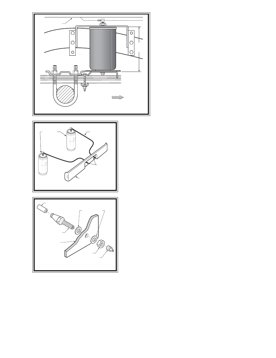
Align the air spring so that it is as close to vertical as possible and
the upper and lower brackets are parallel. Position the upper bracket
so that the distance between the upper and lower brackets is
approximately 7-1/2" see Figure "B". There should be 1/4" to 1/2" of
clearance between the fitting on the top of the air spring and the bottom
of the vehicle's body. Note that the two lower holes will be used to
attach the forward flange to the frame rail while the rear flange will use
the upper mounting holes see Figure "B". Using the mounting holes
in the upper bracket as a template, mark the location of the holes to be drilled in the frame rail with a center punch. Drill
four 7/16" holes on the center marks, making sure that any brake, fuel, or electrical lines inside the frame rail will not
be damaged by the drill see Figure "B".
S
TEP
5 - A
TTACH
THE
UPPER
BRACKET
Once the holes have been drilled in the frame rail, attach the upper bracket using the supplied 3/8" -16 x 1-1/2" hex
bolts, large flat washers, and the 3/8" -16 flanged hex nuts see Figure "A". Tighten the 3/8" -16 x 3/4" flanged hex
bolt securing the air spring to the lower bracket.
Figure "B"
Figure "D"
Figure "C"
PUSH-TO-CONNECT
INFLATION VALVE
BODY OF
VEHICLE
AIR LINE
FLAT WASHER
HEX NUT
VALVE CAP
7-1/2”
FRAME
FRONT
PASSENGER’S SIDE
VEHICLE
BODY
AIR HOSE
INFLATION
VALVES
BUMPER
AIR
SPRINGS