Rite-Ride 2377 User Manual
Page 3
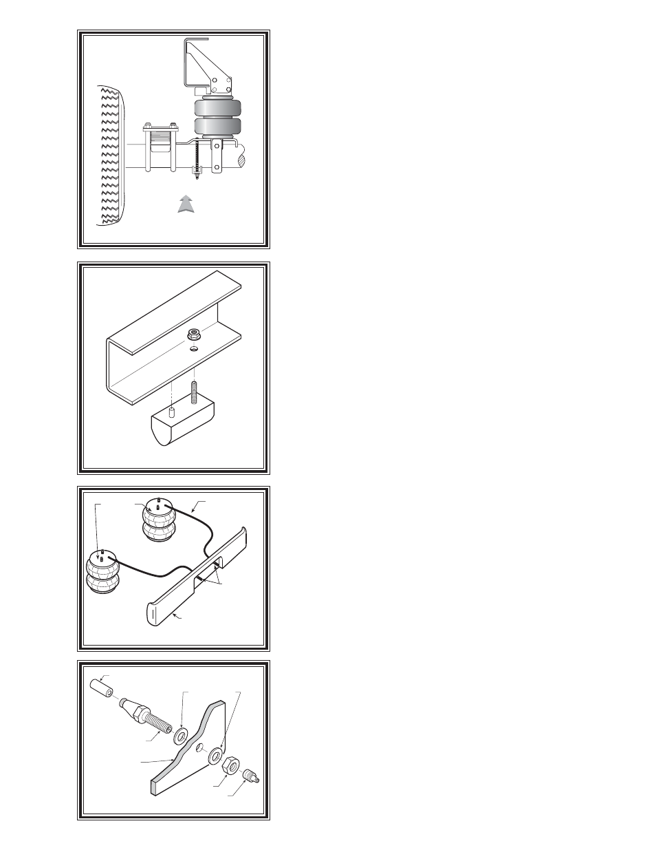
FIGURE "B"
FIGURE "C"
STEP 1 – PREPARE THE VEHCICLE
With the vehicle on a solid, level surface chock the front wheels.
Remove the jounce bumper located under the frame rail, see Figure
“C”. The jounce bumpers and nuts will not be reused with this kit.
STEP 2 – PRE-ASEMBLE THE KIT
This kit contains two different upper brackets, one for the left side
and one for the right side. Preassembly will begin with left side of the
vehicle. All pictures depict the installation on the left side unless noted
otherwise. Install one 3/8"-16 x 2 ½” carriage bolt into the upper
bracket, see Figure “A”. Next, select one of the air springs and install
the upper left bracket using the 5/8"-18 Nylon jam nut. Install the air
fitting as shown in Figure “A”. Tighten the air fitting securely to engage
the orange thread sealant.
Select a lower bracket and then insert two 3/
8"-16 x 6" carriage bolts through the square holes. Next, secure the
lower bracket to the air spring assembly using the 3/8"-16 x ¾” hex head
bolt as shown in Figure “A”. Double check the orientation of both
brackets before attempting installation.
STEP 3 – INSTALL ASSEMBLY ON THE VEHICLE
Insert the 2 ½” carriage bolt from the upper bracket assembly
through the hole provided by the removal of the jounce bumper. Make
sure that the brake line bracket is inserted over the carriage bolt. Place
the lower bracket on top of the axle and position it so that it is flush against
the U-bolts that secure the axle. Once properly positioned, fasten the
upper bracket to the frame using a 3/8"-16 flange lock nut. Attach the
upper left brace to the upper bracket using four 3/8"-16 x1" bolts and
3/8"-16 flange lock nuts as shown in Figure “A”. Next, insert the 5/
16"-24 x 1" hex bolt and flat washer in the upper left brace through the
frame. Secure using a 5/16"-24 flanged lock nut. Attach the lower
bracket to the leaf stack using the 3/8"-16 x 6" carriage bolts installed
earlier and bracket strap as shown in Figure “A” and “B”. The
bracket strap is used to clamp the lower bracket to the axle, see Figures
“A and B”. Fasten using the 3/8"-16 flange lock nuts. Place the lower
support brace on back side on the lower bracket and attach it to the
bracket using 3/8"-16 x 1" hex head bolt and 3/8"-16 flange lock nut and
then attach the bottom part of the brace to the shock bracket on the axle
using a 3/8"-16 x 1" hex head bolt and 3/8"-16 nut stick, as shown in
Figure “A”. Note: the top of the lower support brace should be
even with the lower bracket.
STEP 5 – INSTALLATION OF PASSENGER’S SIDE
Follow steps 1-3 for assembly and installation of the passenger’s
side assembly. Note, reverse any orientations for the passenger's
side installation.
DRIVER'S SIDE
FRONT
AIR HOSE
INFLATION
VALVES
BUMPER
AIR
SPRINGS
FIGURE "D"
AIR LINE
PUSH-TO-CONNECT
INFLATION VALVE
FLAT WASHER
HEX NUT
VALVE CAP
BODY OF
VEHICLE
FIGURE "D"