Step 1—prepare the vehicle, Step 2—pre-assemble the kit, Step 3—installing the assembly to the vehicle – Rite-Ride 2251 User Manual
Page 3: Step 5—install the air line and inflation valve
STEP 1—PREPARE THE VEHICLE
Place the vehicle on a solid level surface. Remove negative battery cable.
Take necessary safety precautions such as using wheel chocks when
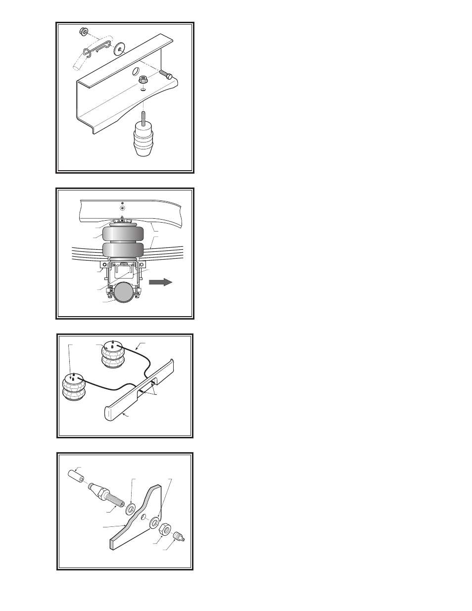
working on your vehicle. Remove the jounce bumpers and the driver side
brake line clip, bolt, and nut as shown in
Figure “B”. This vehicle does
not have to be jacked up to install the kit.
STEP 2—PRE-ASSEMBLE THE KIT
Select one air spring and one upper bracket from your kit. Insert the
1-1/2" carriage bolt upward into square space in upper bracket. Attach
the upper bracket to the air spring using the 3/8"-16 flange lock nuts.
Install the brass air fitting into the air entrance hole and tighten securely
to engage the orange thread sealant to ensure proper seal.
L
ower
bracket
assembLy
Select one lower bracket and one lower brace from your kit. Fasten the
lower brace to the lower bracket using the 3/8"-16 x 1" hex bolts and lock
nuts as shown in
Figure “A”. Assemble the lower bracket assembly to
the air helper spring using the 3/8"-16 x 3/4" hex bolt. Before tightening
the 3/8"-16 hex bolt, rotate the air spring so that the outside vertical edge
of the upper bracket is parallel with the front face of the lower bracket
and brace assembly,
see Figure “A”.
STEP 3—INSTALLING THE ASSEMBLY TO THE VEHICLE
Place the assembly on the vehicle by installing the upper bracket so
that it lays against the outside of the frame rail. Insert the carriage bolt
in the upper bracket to the existing hole in the frame rail from the jounce
bumper removal. Attach with a 3/8"-16 flange lock nut. The lower brace
will sit on the axle, and the lower bracket will rest on the jounce bumper
pad,
refer to Figure “A” and “C”. Push the lower bracket toward the
leaf spring stack until it rests next to the leaf spring “U” bolts.
Attach the upper bracket to the frame rail using the 2 existing holes
in the frame rail and the 3/8"-16 x 1-1/2" hex bolts, 3/8"-16 flange lock
nuts, and 3/8" flat washers (flat washer used only for the larger hole in
frame). NOTE: The break line clip shown in
Figure “A” and “B” exists
only on the driver's side of the vehicle. On the driver’s side, the bolt will
reattach the clip outside of the upper bracket as shown. The 3/8" flat
washer on the outside of the frame rail is used only on the driver’s side
to hold the brake line clip in place. No washer is used on the outside of
the passenger’s side frame rail.
Install the bail clamp around the casting as shown in
Figure “A”.
Insert the bail clamp through the holes in the lower bracket as shown in
Figure “A”. Install 3/8"-16 flange lock nuts and draw the lower bracket
next to the leaf spring “U” bolts. Using the 3/8"-16 x 3" carriage bolts
attach the bracket straps to the lower brace making sure the bracket
straps are securing the kit assembly to the axle,
refer to Figure “C”.
STEP 4—INSTALLATION OF THE
PASSENGER’S SIDE ASSEMBLY
Follow steps 1-3 with reverse orientations for assembly and installation
of the passenger's side assembly. (Note that on the right side (passenger
side), the assembly will sit close to the heat shield located on the front
of the axle.)
STEP 5—INSTALL THE AIR LINE AND INFLATION VALVE
Uncoil the airline tubing and cut it into two equal lengths.
DO NOT FOLD
OR KINK THE AIRLINE TUBING. Try to make the cut as square as pos-
sible. Insert one end of the airline tubing into the air fitting installed in the
top of the air helper spring. Push the airline tubing into the fitting as far
as possible,
refer to Figure “A”.
Select a location on the vehicle for the air inflation valves. The loca-
tion can be on the bumper or the body of the vehicle, as long as it is
in a protected location so the valve will not be damaged, but maintain
accessibility for the air chuck as shown in
Figure “D”. Drill a 5/16" hole
Figure “D”
AIR HOSE
INFLATION
VALVES
BUMPER
AIR
SPRINGS
Figure “E”
AIR LINE
PUSH-TO-CONNECT
INFLATION VALVE
FLAT WASHER
HEX NUT
VALVE CAP
BODY OF
VEHICLE
Figure “C”
AIR HELPER
SPRING
LOWER BRACE
LOWER BRACKET
BRACKET STRAP
AXLE
LEAF STACK
UPPER BRACKET
FRAME RAIL
JOUNCE
BUMPER
PAD
DRIVER’S SIDE
FRONT
Figure “B”