Rite-Ride 2350 User Manual
Page 3
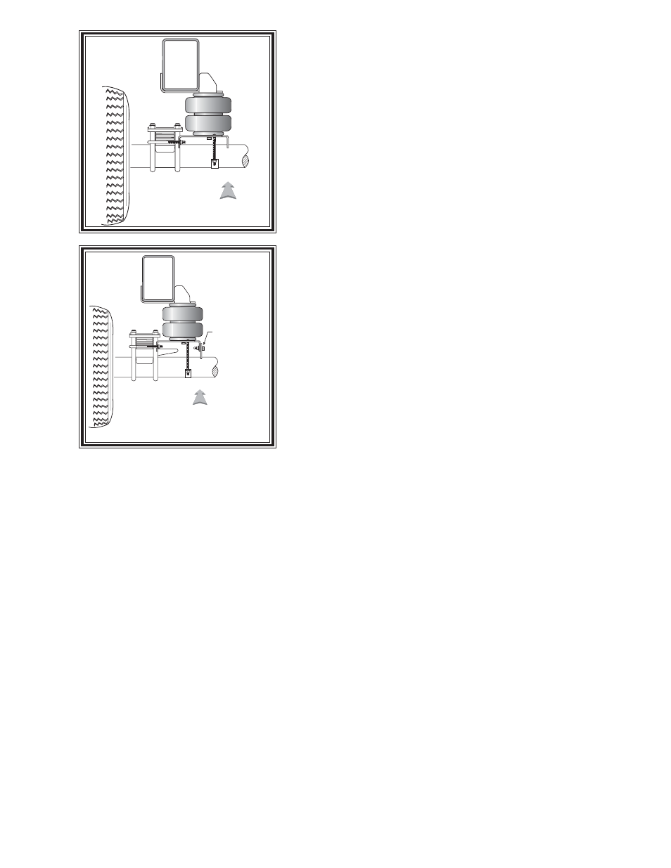
DRIVER'S SIDE
FRONT
4X2 ONLY
FIGURE "B"
FIGURE "C"
S
TEP
1 - P
REPARE
THE
VEHICLE
Remove the negative battery cable.With the vehicle on a solid, level
surface chock the front wheels. Raise the vehicle by the rear axle and
remove the rear wheels. After the removal of the wheels lower the
vehicle so the axle rests on jack stands rated for your vehicles weight.
Remove the jounce bumper located under the frame rail.
S
TEP
2 - P
REASSEMBLE
THE
KIT
Select one air helper spring and an lower bracket from your kit.
Next, place the 3/8"-16 x 5 1/2" carriage bolts into the square holes on
the lower bracket. Fasten the lower bracket using a 3/8"-16 x 3/4" hex
head bolt finger tight.
See Figure "A".
S
TEP
3 - U
PPER
BRACKET
INSTALLATION
Install the upper bracket on the frame using the 10mm x 30mm flat head
allen bolt, see Figure "A". This will be located where the jounce
bumper was removed. Attach the air spring to the upper bracket with
the 5/8"-18 Nylon jam nut. The combination stud will use the inner most
hole and the "button" on the air spring will be aligned with the outer most
hole on the upper bracket(see Figure "A"). Note: On the exhaust
side of the truck, a heat shield will be required. Please see heat
shield manual. Install the air fitting into the air spring and tighten
securely to engage the orange thread sealant, see Figure "A".
S
TEP
4 - L
OWER
BRACKET
INSTALLATION
The lower bracket will rest on the axle with the outter portion placed
between the U-bolts that hold the leaf stack to the axle. Insert the bail
clamp into the two holes on the lower bracket from outside the leaf stack and secure with the 3/8"-16 hex
nuts(Figures "A" & "B") Push the axle strap onto the carriage bolts from the underside of the axle and secure
it using the 3/8"-16 hex nuts see Figure "A".
On 4X4 modles, attach the lower brace to the lower bracket using the 3/8-16 x 1" hex head bolts and 3/8-16
hex nuts, see Figures "A" & "C". The lower bracket will rest on the "toung" instead of the axle. The rest of the
attachments are the same(Figure "A" ).
After everything is aligned, tighten the 3/8"-16 hex bolt on the bottom of the air spring.
S
TEP
5 - I
NSTALLATION
TO
THE
PASSENGER
'
S
SIDE
ASSEMBLY
Reverse any orientations when assembling and installing the right, or passenger, side of the vehicle.
S
TEP
6 - I
NSTALL
THE
AIR
LINE
AND
THE
INFLATION
VALVE
Uncoil the air line tubing and cut it into two equal lengths. DO NOT FOLD OR KINK THE TUBING. Try
to make the cut as square as possible. Insert one end of the tubing into the elbow fitting installed in the top of the
air helper spring. Push the tubing into the fitting as far as possible.
Select a location on the vehicle for the air inflation valves. The location can be on the bumper or the body of
the vehicle, as long as it is in a protected location so the valve will not be damaged, but maintain accessibility for
the air chuck, see Figure "F". Drill a 5/16" hole and install the air inflation valve using two 5/16" flat washers
per valve as supports, see Figure "E". Run the tubing from the air helper spring to the inflation valve, routing
it to avoid direct heat from the engine, exhaust pipe, and away from sharp edges. Thermal sleeves have been
provided for these conditions. If a thermal sleeve is required simply slide the sleeve over the air line tubing to the
location requiring protection. The air line tubing should not be bent or curved sharply as it may buckle. Secure
the tubing in place with the nylon ties provided. Push the end of the air line tubing into the inflation valve as illustrated,
see Figure "E".
DRIVER'S SIDE
FRONT
4x4 ONLY
USE LOWER BRACE
FOR 4X4 ONLY