Step 1 – prepare the vehicle, Step 2— attach the upper bracket, Step 3a— attach the lower bracket (4wd) – Rite-Ride 2525 User Manual
Page 3: Step 3b— attach the lower bracket (2wd), Step 4— attach the frame bracket to the frame, Step 5— installing the assembly to the vehicle
STEP 1 – PREPARE THE VEHICLE
With the vehicle on a solid, level surface, chock the front wheels. Raise
the vehicle by the rear axle and set on jack stands rated for your vehicles
weight. Remove the real wheels. Remove the jounce bumpers from the
under side of the frame rail. The jounce bumper will not be re-used with
the kit, but the bolt will be re-used.
STEP 2— ATTACH THE UPPER BRACKET
Select one air helper spring and one upper bracket from your kit. Insert
the studs of the air spring into the mounting holes of the upper bracket.
Make sure the air inlet is visible through the large access hole. Fasten
the upper bracket to the air spring using the 3/8"-16 flange nuts, see
Figure “A”. Install the elbow fitting into the air spring through the large
access hole in the upper bracket. Tighten the air fitting securely to engage
the orange thread sealant. Position the fitting to point to the anticipated
location of the air inflation valves.
STEP 3A— ATTACH THE LOWER BRACKET (4WD)
Select the left lower bracket and fasten it to the air spring with a 3/8"-16
x 3/4" flange bolt (finger tight). Figure “B”.
STEP 3B— ATTACH THE LOWER BRACKET (2WD)
Select the left lower bracket and spacer and attach them to the air spring
with a 3/8"-16 x 2" flange hex bolt (finger tight). Open end of the spacer
should mount towards lower bracket. See Figure “C”.
STEP 4— ATTACH THE FRAME BRACKET TO THE FRAME
Attach the left frame bracket to the bottom of the frame reusing the jounce
bumper bolt in the hole from the jounce bumper removal. Next, insert
the 3/8"-16 x 1" hex head bolts through the left frame bracket and into
the holes on the outside of the frame. Secure with framehole brackets
inserted through the hole on the inside of the frame. See Figure “A”.
DO NOT OVER TIGHTEN! 20 FT/LBS Max.
STEP 5— INSTALLING THE ASSEMBLY TO THE VEHICLE
Place the assembly on the leaf stack over the spring retainer and align
the holes in the upper bracket with the holes in the left frame bracket.
Install four, 3/8" x 1" hex head bolts and fasten using 3/8"-16 flange nuts.
Secure the left lower bracket to the leaf stack using bail clamps and 3/8"-
16 flange nuts. Once aligned, tighten the bolt holding the bottom of the
air spring to the lower bracket. See Figures “A”, “B” & “C”.
STEP 6 — INSTALLATION TO THE PASSENGER’S
SIDE ASSEMBLY
Reverse any orientations when assembling and installing the right, or
passenger, side of the vehicle.
STEP 7—INSTALL THE AIR LINE AND THE
INFLATION VALVE
Uncoil the air line tubing and cut it into two equal lengths.
DO NOT FOLD
OR KINK THE TUBING. Try to make the cut as square as possible. Insert
one end of the tubing into the elbow fitting installed in the top of the air
helper spring. Push the tubing into the fitting as far as possible. Select
a location on the vehicle for the air inflation valves. The location can be
on the bumper or the body of the vehicle, as long as it is in a protected
location so the valve will not be damaged, but maintain accessibility for
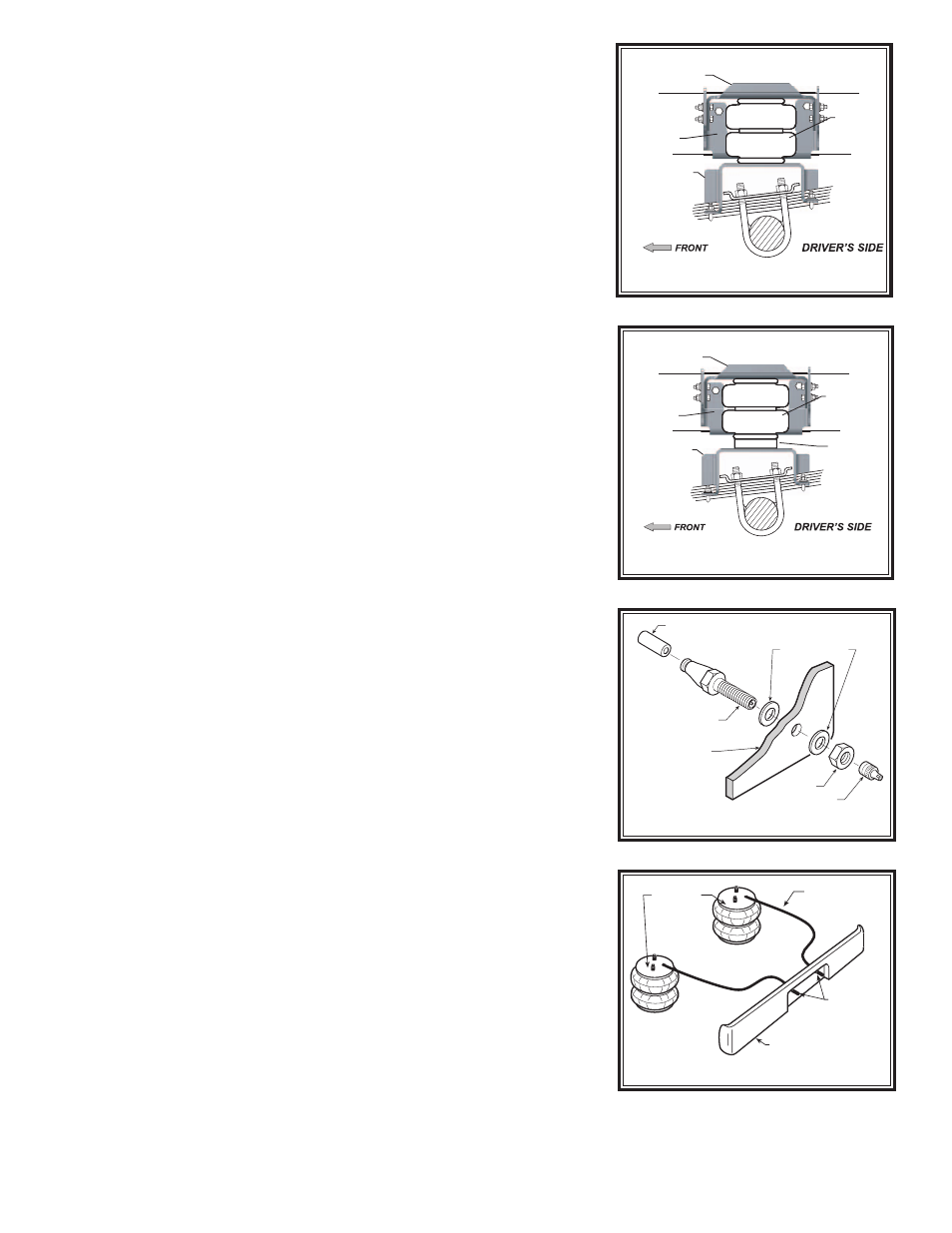
the air chuck, see Figure “E”. Drill a 5/16" hole and install the air inflation
valve using two 5/16" flat washers per valve as supports, see Figure “D”.
Run the tubing from the air helper spring to the inflation valve, routing it
to avoid direct heat from the engine, exhaust pipe, and away from sharp
edges. Thermal sleeves have been provided for these conditions. If a
thermal sleeve is required simply slide the sleeve over the air line tubing
to the location requiring protection. The air line tubing should not be bent
or curved sharply as it may buckle. Secure the tubing in place with the
nylon ties provided. Push the end of the air line tubing into the inflation
valve as illustrated, see Figure “D”.
4WD
ONLY
LOWER
BRACKET
FRAME
BRACKET
UPPER
BRACKET
AIR
SPRING
Figure “B”
SPACER
2WD ONLY
2WD
ONLY
LOWER
BRACKET
FRAME
BRACKET
UPPER
BRACKET
AIR
SPRING
Figure “C”
Figure “D”
Figure “E”
AIR LINE
PUSH-TO-CONNECT
INFLATION VALVE
FLAT WASHER
HEX NUT
VALVE CAP
BODY OF
VEHICLE
AIR HOSE
INFLATION
VALVES
BUMPER
AIR
SPRINGS