Rite-Ride 2535 User Manual
Page 4
nuts onto the bail clamp and tighten the 3/8" flange nuts. See Figure “A”.
Insert the carriage bolts thru the saddle bracket being very careful
not to chaff or pinch the brake lines on the axle. Next, push the axle strap
onto the bottom of the axle and over the carriage bolts. When the flange
nuts are tightened, they will draw the axle strap into place.
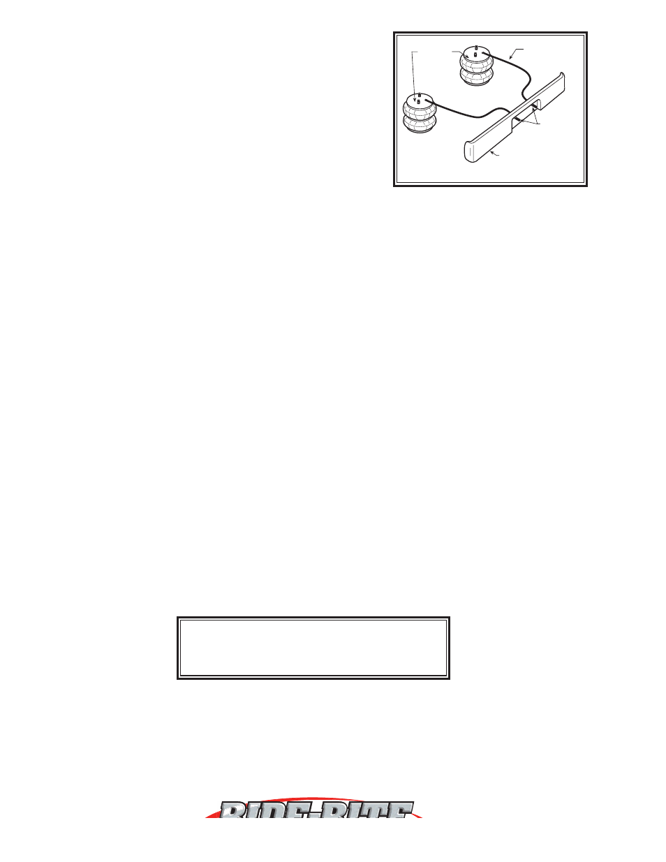
STEP 5— AIR LINE INSTALLATION
Uncoil the air tubing and cut it into two equal lengths.
DO NOT FOLD OR
KINK THE TUBING. Try to make the cut as square as possible. Insert
one end of the tubing into the elbow fitting installed in the top of the air
helper spring. Push the tubing into the fitting as far as possible.
Select a location on the vehicle for the air inflation valves. This can
be on the bumper or the body of the vehicle, as long as it is protected
so the valves will not be damaged. Drill a 5/16" hole and install the air
inflation valve using two 5/16" flat washers per valve as supports. Route
the tubing from the air helper spring to the inflation valve, avoiding direct heat from the engine, exhaust pipe, and
away from sharp edges. The air line tubing should not be bent or curved sharply as it may buckle with time. Secure
the tubing in place with the nylon ties provided. Push the end of the air line tubing into the inflation valve as far as
possible. See Figures “D” & “E”.
STEP 6— CHECK THE SYSTEM
Final inspection. Visually check for loose attaching bolts. Make sure that no part of the truck is rubbing against the
air springs. Again, make sure that the truck’s brake lines are not pinched or being rubbed by any part of your Ride-
Rite
TM
kit.
Once the inflation valves are installed, inflate the air helper springs to
50 psi and check the fittings for air leaks
with an applied solution of soap and water. If a leak is detected, deflate the air spring by depressing the valve core.
The tubing can easily be removed from the fittings by pushing the collar towards the body of the fitting while pulling
out the tube. Next, check the tubing connection to ensure that the air tubing is cut as square as possible and that it
is pushed completely into the fitting.
If a leak is detected where the air fitting screws into the air spring, gently tighten the air fitting into the spring until
the leak stops. Also, check the core of the inflation valve. This valve core can be tightened using the cap. Re-inflate
the air spring and check for leaks again if needed. This now completes the installation. Reconnect the battery cable
and remove the wheele chocks.
NOTE: THE OPERATING PRESSURE OF THIS KIT IS 5 PSI MIN. TO 100 PSI MAX.
Too much air pressure in the air helper springs will result in a firmer ride, while too little air pressure will allow the
air helper spring to bottom out over rough conditions. Too little air pressure will also not provide the improvement
in handling that is possible.
TO PREVENT POSSIBLE DAMAGE MAINTAIN A MINIMUM OF 5 psi IN THE AIR
HELPER SPRINGS AT ALL TIMES.
Once the air helper springs are installed, it is recommended that the vehicle not be lifted by the frame, as over-
extension may occur, resulting in damage to the air helper springs. However, should it become necessary to raise
the vehicle by the frame, deflate both air helper springs completely.
AIR HOSE
INFLATION
VALVES
BUMPER
AIR
SPRINGS
NOTE:
MIN PRESSURE
5 PSI
MAX PRESSURE (LOADED)
100 PSI
www.riderite.com
Figure “E”