Rite-Ride 2299 User Manual
Page 4
STEP 6 — INSTALL THE AIRLINE AND INFLATION VALVE
Uncoil the airline tubing and cut it into two equal lengths. DO NOT
FOLD OR KINK THE AIRLINE TUBING. Try to make the cut as
square as possible. Insert one end of the airline tubing into the air fit-
ting installed in the top of the air helper spring. Push the airline tubing
into the fitting as far as possible, see Figure “A”.
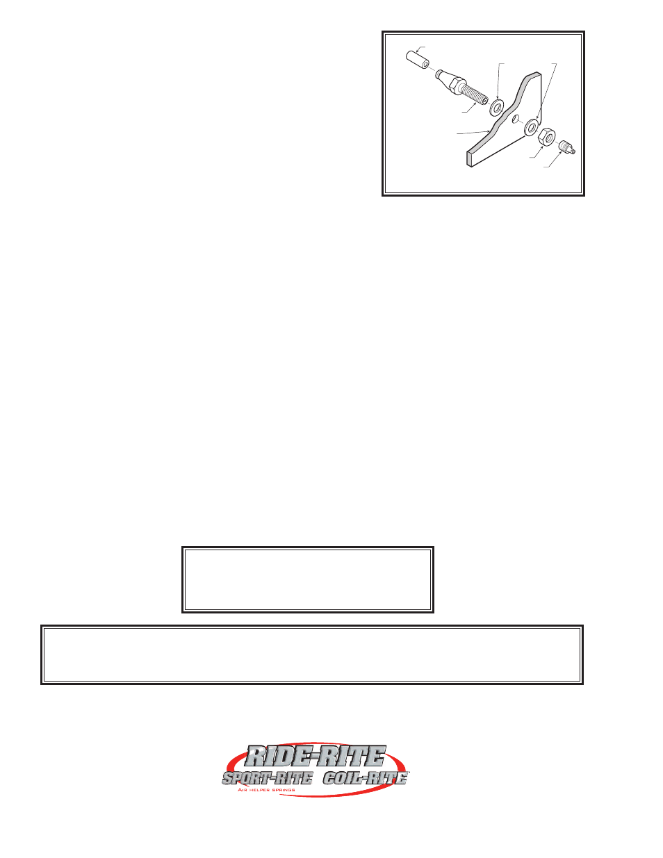
Select a location on the vehicle for the air inflation valves. The
location can be on the bumper or the body of the vehicle, as long
as it is in a protected location so the valve will not be damaged, but
maintain accessibility for the air chuck, see Figure “D”. Drill a 5/16"
hole and install the air inflation valve using two 5/16" flat washers per
valve as supports, see Figure “E”. Run the airline tubing from the
air helper spring to the valve, routing it to avoid direct heat from the
engine, exhaust pipe, and away from sharp edges. Thermal sleeves
have been provided for these conditions. The airline tubing should not
be bent or curved sharply as it may buckle. Secure the airline tubing in place with the nylon ties provided. Push the
end of the airline tubing into the inflation valve as illustrated, see Figure “E”.
STEP 7— CHECK THE AIR SYSTEM
Once the inflation valves are installed, inflate the air helper springs to 70 psi and check the fittings for air leaks.
Using a spray bottle, apply a solution of soap and water to the fittings. If a leak is detected at an airline tubing con-
nection then check to make sure that the airline tube is cut as square as possible and that it is pushed completely
into the fitting. The airline tubing can easily be removed from the fittings by exhausting all the pressure in the air
springs and then pushing the collar towards the body of the fitting and then, with a pull, remove the airline tubing.
Re-install the tubing and reinflate the air springs and check for leaks as noted above. If a leak is detected where the
air fitting screws into the spring, just screw the air fitting into the air spring until the leak stops.
This now completes the installation. Reattach the negative battery cable and remove the wheel chocks from the
front wheels. Before proceeding, check once again to be sure you have proper clearance around the air springs.
With a load on your vehicle and the air helper springs inflated, you must have at least 1/2" clearance around the air
springs. As a general rule, the air helper springs will support approximately 50 lbs. of load for each psi of inflation
pressure (per pair). For example, 50 psi of inflation pressure will support a load of 2500 lbs. per pair of air helper
springs.
FOR BEST RIDE use only enough air pressure in the air helper springs to level the vehicle when viewed
from the side (front to rear). This amount will vary depending on the load, location of load, condition of existing sus-
pension and personal preference.
NOTE: Too much air pressure in the air helper springs will result in a firmer ride, while too little air pressure will
allow the air helper spring to bottom out over rough conditions. Too little air pressure will not provide the improve-
ment in handling that is possible. TO PREVENT POSSIBLE DAMAGE MAINTAIN A MINIMUM OF 5 psi IN THE
AIR HELPER SPRINGS AT ALL TIMES.
NOTE:
Once the air helper springs are installed, it is recommended that the vehicle not be lifted by
the frame, as over-extension may occur, resulting in damage to the air helper springs. However, should
it become necessary to raise the vehicle by the frame, deflate both air helper springs completely.
www.ride-rite.com
NOTE:
MIN PRESSURE
5 PSI
MAX PRESSURE (LOADED)
100 PSI
FIGURE “E”
AIR LINE
PUSH-TO-CONNECT
INFLATION VALVE
FLAT WASHER
HEX NUT
VALVE CAP
BODY OF
VEHICLE
(Step 6)