Rite-Ride 2299 User Manual
Page 3
NOTE:
Please read thorough this manual completely before installing the air
spring kit on your vehicle.
STEP 1 — PREPARE THE VEHICLE
With the vehicle on a solid, level surface chock the front wheels.
Remove the negative battery cable. Your vehicle is equipped with
rubber jounce bumpers. The jounce bumpers are bolted to the frame
above the axle. Remove the jounce bumpers from the vehicle.
STEP 2 — PRE-ASSEMBLE THE KIT
Select a lower bracket from your kit and determine which side of the
bracket fits most snugly between the axle U-bolts as shown in Figure
“A”. NOTE: The smaller side is for the gasoline engine axle and
the larger side is for Diesel engine axle. Select one air spring, bail
clamp and lower bracket from your kit. Place the bail clamp in the
correct position in the slot of the lower bracket for your vehicle. Install
the air spring to the lower bracket using the hole for your vehicle with
a 3/8"-16 x 3/4" flange head bolt that is mounted finger tight. Please
see the lower right section of Figure “A”. The bolt will be tight-
ened up in STEP 5. NOTE: On 2011 and newer RAM 2500 gasoline
engine and Power Wagons, a spacer will be need to be installed
between the air spring and the lower bracket. If the spacer is
used, use the 3/8"-16 x 2" flange head bolt. Next, install the male
air fitting into the air inlet in the combo stud of the air spring. Tighten
the air fitting securely to engage the orange thread sealant.
STEP 3A—INSTALLING THE UPPER BRACKET TO THE
VEHICLE (TWO WHEEL DRIVE)
Select an upper bracket and upper brace from your kit. Install the
upper bracket to the frame using two 10 mm x 30 mm flat head bolts,
see Figure “A”. Next, attach the brace using the lower set of holes
that are marked “2WD” using four 3/8"-16 x 1" hex head bolts and four
3/8”-16 flange lock nuts, as shown in Figure “B”.
STEP 3B—INSTALLING THE UPPER BRACKET TO THE
VEHICLE (FOUR WHEEL DRIVE)
Select an upper bracket and upper brace from your kit. Install the
upper bracket to the frame using two 10 mm x 30 mm flat head bolts,
see Figure “A”. Next, attach the brace using the upper set of holes
that are marked “4WD” using four 3/8"-16 x 1" hex head bolts and four
3/8"-16 flange lock nuts, as shown in Figure “B”.
STEP 4—INSTALLING THE ASSEMBLY TO THE VEHICLE
Position the lower bracket and air spring assembly from STEP 2 on
the axle as shown in Figure “A”. Put the large threaded stud though
the large hole on the upper bracket and the locating pin of the air
spring in the small hole on the upper bracket as shown in Figure “A”.
Make sure the aliment pin is in the locating hole before fasting
air spring to the upper bracket. Fasten the air spring to the upper
bracket using ¾"-16 hex head nut and ¾" star washer. Fasten the
lower bracket to the axle housing using the bail clamp and the axle
clamp bracket and two 3/8"-16 locking flange nuts securely. Once the
lower bracket orientation has been set, tighten the 3/8"-16 x ¾" flange
bolt that was installed in STEP 2.
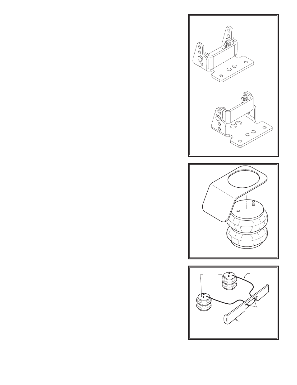
STEP 5—INSTALLATION OF THE PASSENGER’S SIDE
ASSEMBLY
Before following STEPS 1-4 with reverse orientations for assembly
and installation of the passenger’s assembly, a heat shield will need
to be mounted between the upper bracket assembly and the top plate
of the air spring, see Figure “C”. Position the heat shield directly
between the closest heat source and the air spring. Ensure that the
heat shield will not interfere with normal operation of the air spring
or the vehicle’s suspension. Do not position the heat shield directly
above the axle, as it may contact the axle on full suspension travel.
HEAT SHIELD
FIGURE “C”
2W
D
4W
D
Two Wheel Drive Setting
2W
D
4W
D
Four Wheel Drive Setting
FIGURE “B”
FIGURE “D”
AIR HOSE
INFLATION
VALVES
BUMPER
AIR
SPRINGS
(Step 3)
(Step 5)
(Step 6)