1 - p, 2 - p, 3 - p – Rite-Ride 2040 User Manual
Page 3: 4 - i, 5 - i
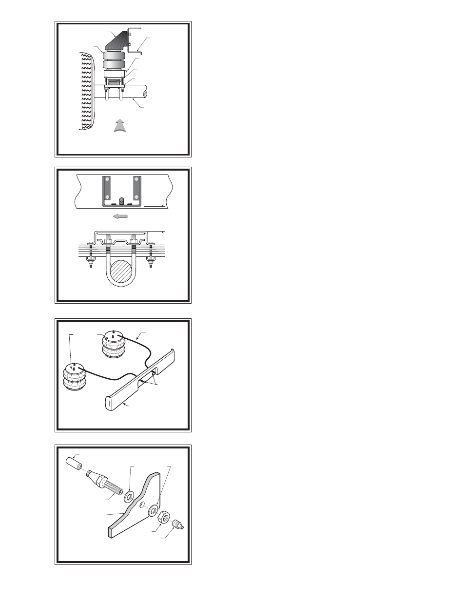
FIGURE "B"
FIGURE "C"
FIGURE "D"
FIGURE "E"
S
TEP
1 - P
REPARE
THE
VEHICLE
Remove the negative battery cable. With the vehicle on a solid, level surface
chock the front wheels. Raise the vehicle by the axle and remove the rear wheels.
After the removal of the wheels, lower the vehicle so the axle rests on jack stands
rated for your vehicle's weight. This installation assumes that there is no load
in the bed of the truck.
S
TEP
2 - P
RE
-
ASSEMBLE
THE
KIT
Select one air helper spring and an upper bracket from your kit. Align the studs
of the air spring with the mounting holes of the upper bracket and insert. Make
sure the air inlet is visible through the large access hole in the upper bracket.
Fasten the upper bracket to the air spring using the 3/8"-16 hex nut, see Figure
"A". Next, install the brass elbow fitting into the air spring through the large
access hole in the upper bracket. Tighten the air fitting securely to engage the
orange thread sealant. Position the elbow to point in the anticipated location
of the air inflation valve see Figures "A" & "D". Select one lower bracket and
orient the bracket so the lip of the lower bracket will be facing the inside of the
vehicle see Figures "A" & "B". Attach the lower bracket to the air spring using
3/8"-16 x 3/4" flanged hex bolt through the center slot.
S
TEP
3 - P
RE
-
FIT
AND
MARK
/
DRILL
HOLES
Position the air spring assembly on the leaf spring stack. The lower bracket
should straddle the leaf spring retainer and be centered front-to-back on the leaf
spring see Figure "C". The upper bracket should be flush against the frame see
Figures "A" & "B". Make sure that the lip of the lower bracket is positioned toward
the inside of the vehicle. The upper bracket should be positioned so that the air spring
is vertically aligned between the upper and lower brackets.
It may be necessary to slide the entire air spring assembly fore or aft along the
leaf spring in order to provide clear mounting. Before marking and drilling the
holes for the upper bracket, make sure the mounted height of the air spring is
between 5" - 6-1/2", and the upper and lower brackets are as parallel as possible
see Figure "C". Mark the four holes to be drilled in the frame with a center punch
using the upper bracket as a template, then remove the air spring assembly. Before
drilling the holes make sure all electrical, brake and fuel lines are cleared from
the path of the drill. Damage to lines can be avoided by inserting a piece of wood
between the frame rail and any lines in the path of the drill. Drill the four holes in
the frame rail using a 3/8" drill bit see Figure "A".
S
TEP
4 - I
NSTALL
THE
ASSEMBLY
TO
THE
VEHICLE
After drilling the holes in the frame rail, place the assembled air spring back
on the leaf stack making sure the lower bracket is placed over the retainer see
Figures "A" & "C". Fasten the upper bracket to the frame rail using the3/8"-
16 x 1-1/2 hex bolts, 3/8" flat washers, and 3/8" hex nuts on the inside of the
frame rail see Figure "A". Next, attach the lower bracket to the leaf spring
stack. Use the bracket strap and fasten the air spring assembly to the leaf stack
using the 3/8"-16 x 7" carriage bolts and 3/8"-16 flanged lock nuts see Figure
"A".
S
TEP
5 - I
NSTALL
THE
PASSENGER
'
S
SIDE
ASSEMBLY
Reverse any orientations when assembling and installing the air spring to the
right, or passenger, side of the vehicle.
5 - 6-1/2
FRONT
AIR HOSE
INFLATION
VALVES
BUMPER
AIR
SPRINGS
AIR LINE
PUSH-TO-CONNECT
INFLATION VALVE
FLAT WASHER
HEX NUT
VALVE CAP
BODY OF
VEHICLE
FRAME RAIL
UPPER BRACKET
AIR SPRING
UPPER BRACKET
BRACKET STRAP
AXLE
LEAF STACK
DRIVER'S SIDE
FRONT