1 - p, 2 - p, 3 - i – Rite-Ride 2337 User Manual
Page 3: 4 - i, 5 - i
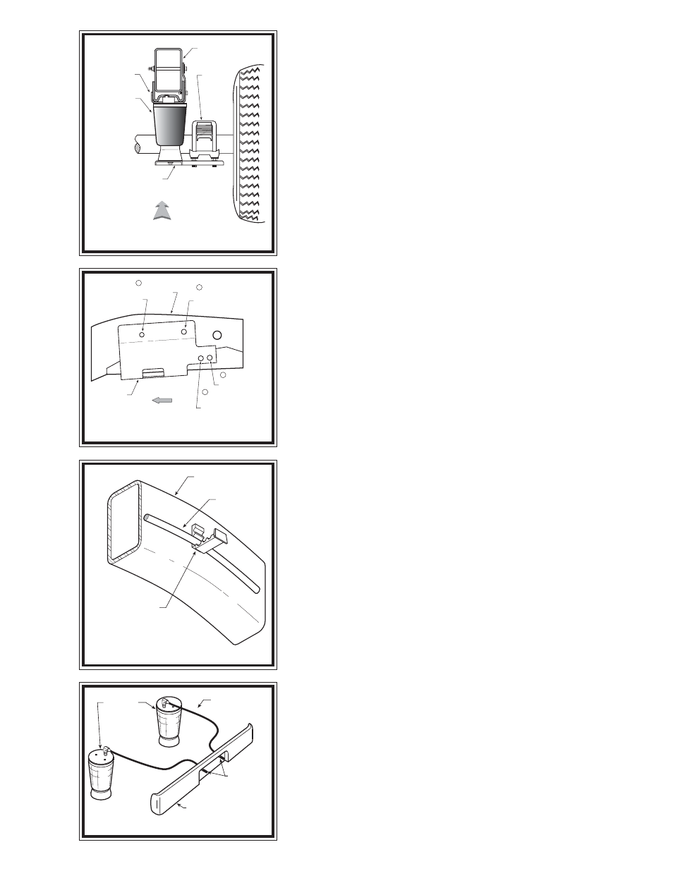
FIGURE "B"
FIGURE "C"
FIGURE "D"
FIGURE "E"
S
TEP
1 - P
REPARE
THE
VEHICLE
Remove the positive battery cable. With the vehicle on a solid, level surface
chock the front wheels. Raise the vehicle by the axle and remove the rear wheels.
After the removal of the wheels, lower the vehicle so the axle rests on jack stands
rated for your vehicle's weight. This installation assumes that there is no load
in the vehicle.
S
TEP
2 - P
RE
-
ASSEMBLE
THE
KIT
Select one air helper spring from your kit. Install the push-to-connect elbow
fitting in the top of the air spring. Tighten the elbow fitting until the nylon ring
is seated then tighten 1/4 turn to seal (Do NOT over tighten). The elbow fitting
swivels and can be positioned in any direction after installation. Select the
upper-left bracket from your kit (marked "L") and align the holes in the air
spring with the holes in the upper bracket. Fasten the bracket to the air spring
using two 3/8" -16 x 3/4" flanged hex bolts see Figure "A". Select the left-side
lower bracket (marked "L") and one round disk from your kit place the round disk
between the lower bracket and the air spring and attach both to the air spring with
a 3/8 -16 x 3/4" flanged hex bolt (finger tight).
S
TEP
3 - I
NSTALL
THE
ASSEMBLY
TO
THE
VEHICLE
Position the lower bracket on the leaf spring retainer below the axle. Three of
the U-bolt studs should protrude through the holes in the lower bracket see
Figures "A" & "B". Attach the lower bracket to the U-bolts with the provided
M16 x 2.0 hex nuts. The hex nuts are self locking.
Cut the air line tubing supplied into two equal lengths. Make sure that the
air line tubing is cut as square as possible and install into the push-to-connect
elbow fitting on the air spring. Install the push-to-connect inflation valve fitting
onto the opposite end of the air line tubing (temporarily). Inflate the air spring
to no more than 10 psi so that the upper bracket straddles the frame, with the
vertical portion of the bracket flush against the outside surface of the frame rail.
The tab at the front of the bracket should recess into the hole in the bottom of
the frame rail see Figure "A".
Refer to Figure "C" for upper bracket alignment and attachment. Visually
align hole# 1 as shown in Figure "C". Using the upper bracket as a template drill
hole# 2 and hole# 3 using a 9/32" drill bit. Install the 3/8" self tapping screws
into the hole just drilled.
Using the open hole (hole# 4) at the top of the bracket as a template, drill
a 7/16" hole through both sides of the frame rail see Figures "A" & "C". The
drill bit must be at least 4-3/4" in length from the tip to the chuck. Before drilling,
open the brake-line bracket on the inside of the frame rail see Figure "D". Insert
a block of wood between the frame rail and the brake-line to prevent the line
from being damaged by the drill. After drilling the hole place the brake line back
into the clip. Secure the upper bracket to the frame with a 3/8" -16 x 5-1/2" bolt
through the drilled holes and secure with a 3/8" -16 flanged lock nut and 3/8"
washers see Figure "A".
Tighten the flanged hex bolt securing the air spring to the lower bracket.
S
TEP
4 - I
NSTALL
THE
PASSENGER
'
S
SIDE
ASSEMBLY
Reverse any orientations when assembling and installing the air spring to the
right, or passenger's side of the vehicle. Follow steps 2 and 3.
S
TEP
5 - I
NSTALL
THE
AIR
LINE
AND
INFLATION
VALVE
Release the air pressure from the air springs and remove the inflation
valve from the end of the air line tubing installed in step 3. Select a location
on the vehicle for the air inflation valves. The location can be on the bumper or
the body of the vehicle, as long as it is in a protected location so the valve will
not be damaged, but still maintain accessibility for the air chuck see Figure "E".
Drill a 5/16" hole and install the air inflation valve using two 5/16" flat washers
per valve as supports see Figure "F". Run the tubing from the air helper spring
AIR HOSE
INFLATION
VALVES
BUMPER
AIR
SPRINGS
VEHICLE
FRAME
OPEN BRAKE-LINE
BRACKET AND PULL
BRAKE LINE AWAY
FROM FRAME
BRAKE
LINE
LEAF
STACK
AIR SPRING
FRAME RAIL
UPPER
BRACKET
DRIVER'S SIDE
REAR
LOWER BRACKET
DRILL 9/32” HOLE,
INSTALL 3/8”
SELF-TAPPING
SCREW
DRILL 9/32” HOLE,
INSTALL 3/8”
SELF-TAPPING
SCREW
DRILL 7/16” HOLE,
INSTALL 3/8” -16 x 5-1/2”
HEX BOLT
UPPER
BRACKET
FRAME
RAIL
4
3
FRONT
LEFT SIDE
VISUALLY ALIGN
HOLES
1
2