Rite-Ride 2423 User Manual
Page 3
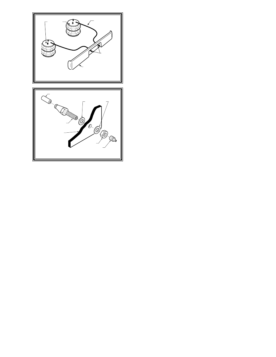
AIR HOSE
INFLATION
VALVES
BUMPER
AIR
SPRINGS
STEP 1 - PREPARE THE VEHICLE
With the vehicle on a solid, level surface chock the front wheels.
Raise the vehicle by the rear axle and remove the rear wheels. After
the removal of the wheels lower the vehicle so the axle rests on jack
stands rated for your vehicles weight. Make sure the negative
battery cable is disconnected from the battery.
STEP 2 - PREASSEMBLE
Select one air helper spring from your kit and the lower right
bracket. Use the 3/8"-16 flat head bolt to secure the bracket to the
air spring. See Figure "A".
Next, select the upper right bracket, two bail clamps, and four
5/16" lock nuts. Place the upper bracket on the frame centered over
the axle as shown in Figure "A". Install the bail clamps over the
frame and through the holes in the upper bracket and loosely fasten
the 5/16" lock nuts. See Figure "A".
STEP 3- INSTALLATION TO THE VEHICLE
Place the air spring assembly on the axle and under the upper
bracket. Insert the large stud into the larger hole and the alignment
pin into the smaller hole. Install the Nylon jam nut onto the air spring
stud then install the air fitting. Tighten the air fitting securely to engage
the orange thread sealant. See Figure "A".
Next, make sure the lower bracket is level on the axle and, using the bracket as a template, drill a 7/16" hole in
the shock mount on the axle as shown in Figure "A". Position the nut plate inside the shock mount and install the
1" hex bolt affixing the lower bracket to the axle.
Place one of the 5 1/2" carriage bolts into the square hole closest to the leaf spring stack. Select the right-side U-
bolt clamp and place it on the vehicle so the large hole is around the forward-most axle U-bolt and the carriage bolt inserts
into the small hole. Install and tighten one 3/8" lock nut. See Figure "A".
Next place two of the 5 1/2" carriage bolts into the remaining square holes on the lower brackets. Place the bracket
clamp onto the carriage bolts from under the axle then install and tighten two 3/8" lock nuts as shown in Figure "A".
Tighten the 5/16" lock nuts on the bail clamp and make sure all brackets are secure.
NOTE: On the right, or passenger's side of the vehicle, a heat shield is required. Please see the heat shield flyer
for proper installation.
STEP 4- INSTALLATION OF THE DRIVER'S SIDE ASSEMBLY
Follow steps 1-4 for assembly and installation of the driver's side assembly.
NOTE: On the left, or driver's side of the vehicle, use some of the provided nylon ties to secure the factory
installed wire loom out of the way to assist in installation.
STEP 5- INSTALL THE AIR LINE AND INFLATION VALVE
Uncoil the air tubing and cut it into two equal lengths. DO NOT FOLD OR KINK THE TUBING. Try to make
the cut as square as possible. Insert one end of the tubing into the air fitting installed in the top of the air helper spring.
Push the tubing into the fitting as far as possible refer to Figure "A".
AIR LINE
PUSH-TO-CONNECT
INFLATION VALVE
FLAT WASHER
HEX NUT
VALVE CAP
BODY OF
VEHICLE
Figure "C"
Figure "B"