1 - p, 2 - p, 3 - i – Rite-Ride 1130 User Manual
Page 3: 4 - i, 5 - i
F
IGURE
"D"
F
IGURE
"C"
S
TEP
1 - P
REPARE
THE
VEHICLE
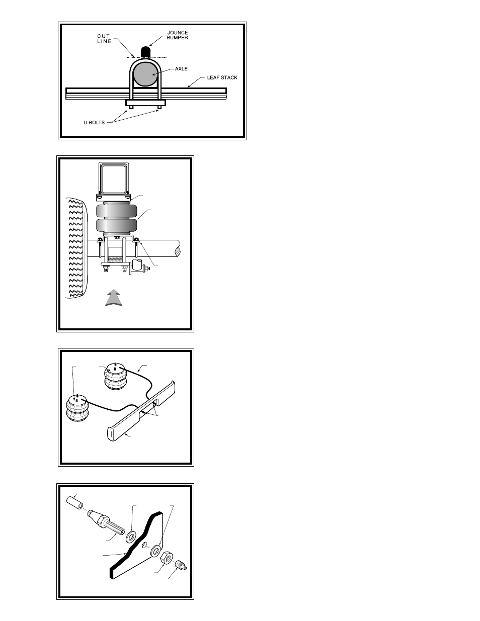
With the vehicle on a solid, level surface chock the front
wheels. Raise the vehicle by the axle and remove the rear wheels.
After the removal of the wheels lower the vehicle so the axle rests
on jack stands rated to support your vehicles weight. Remove the
jounce bumpers located under the frame rail on the axle. The
bumpers will not be reused with this kit.
S
TEP
2 - P
RE
-
ASSEMBLE
THE
KIT
Pre-assembly will begin with the left (driver's) side of the
vehicle. All pictures show the installation on the left side of the
vehicle unless noted otherwise. Select an air spring and one
upper bracket from your kit. NOTE: The upper bracket is off-
center and the air spring extendsfurther on one side of the upper
bracket than the other. The extension, or over-hang, must be on the inboard side
of the truck. See Figure "C". Insert the studs on the air spring into the mounting
holes in the upper bracket, making sure the air inlet hole is visible through the slot
in the bracket. Secure the bracket to the air spring using two 3/8" -16 flanged nuts,
see Figure "A". Install the elbow fitting into the air spring. Tighten the air fitting
securely to engage the orange thread sealant. Position the fitting to point to the
anticipated location of the air inflation valves, see Figure "A" & "D". Select a lower
bracket from your kit. NOTE: The lower bracket is off-center and the air spring
extendsfurther on one side of the lower bracket than the other. The extension, or
over-hang, must be on the inboard side of the truck, the same as the upper bracket.
See Figure "C". Align the slotted hole in the lower bracket with the hole in the
lower plate of the air spring. Fasten the lower bracket to the air spring using a 3/
8" -16 x 3/4" flanged hex bolt. See Figures "A" & "C".
S
TEP
3 - I
NSTALL
THE
ASSEMBLY
TO
THE
VEHICLE
Position the air spring assembly on top of the axle housing as shown in Figures
"A" & "C". It may be necessary to compress the air spring assembly to properly
position the upper bracket. Attach the upper bracket to the bottom of the frame
rail using two bail clamps and 5/16"-18 flange nuts, see Figure "A".
Attach the lower bracket to the axle housing using two U-bolts and four
5/16" -24 flanged nuts, see Figure "A". The lower bracket should fit on the axle
housing without interfering with the brake line. If the brake line is in contact with
the lower bracket, it may be necessary to move the brake line slightly by bending
it away from the contact point. Once the assembly is in place, there must be a
minimum of a 1/2" of clearance around the air spring at all times.
S
TEP
4 - I
NSTALL
THE
PASSENGER
'
S
SIDE
ASSEMBLY
Follow the same procedures when assembling and installing the air spring on
the passenger's side of the vehicle. NOTE: The use of a heat shield is required on
the exhaust side of the vehicle. See Figure "F". The heat shield will mount between
the air spring and the upper bracket. Position the heat shield so it is half way
between the air spring and the closest part of the exhaust. Be sure the heat shield
will not contact any part of the air helper spring kit or the vehicle as the suspension
compresses (i.e. brake lines, axle, shock absorbers, lower bracket, etc.).
S
TEP
5 - I
NSTALL
THE
AIR
LINE
AND
INFLATION
VALVE
Uncoil the air tubing and cut it in two equal lengths. DO NOT FOLD OR KINK
THE TUBING. Make the cut as square as possible. Insert one end of the tubing
into the push-to-connect elbow fitting installed in the top of the air helper spring
as far as possible.
Select a location on the vehicle for the air inflation valves. The location can be
on the bumper or the body of the vehicle, as long as it is in a protected location so
the valve will not be damaged, but still maintain accessibility for the air chuck see
Figure "D". Drill a 5/16" hole and install the air inflation valve using two 5/16" flat
washers per valve as supports see Figure "E". Run the tubing from the air helper
spring to the valve, routing it to avoid direct heat from the engine, exhaust pipe,
and away from sharp edges. Thermal sleeves have been provided for these
conditions. The air line tubing should not be bent or curved sharply as it may
buckle. Secure the tubing in place with the nylon ties provided. Push the end of
the air line tubing into the inflation valve see Figure "E".
AIR HOSE
INFLATION
VALVES
BUMPER
AIR
SPRINGS
LOWER
BRACKET
DRIVER'S SIDE
FRONT
AIR
SPRING
UPPER
BRACKET
FRAME
RAIL
F
IGURE
"E"
AIR LINE
PUSH-TO-CONNECT
INFLATION VALVE
FLAT WASHER
HEX NUT
VALVE CAP
BODY OF
VEHICLE
F
IGURE
"B"