Coil-rite installation procedure – Rite-Ride 4100 User Manual
Page 2
STEP 1—PREPARE THE VEHICLE
With the vehicle on a solid level surface, chock the rear
wheels. Disconnect the negative battery cable. Raise the
front wheels of the vehicle using a lift or platform jack rated
for your vehicle's weight. Lower the vehicle frame onto
jack stands rated for your vehicle's weight, allowing the
suspension to hang freely. (DO NOT use wood or concrete
blocks to support the weight of the vehicle.)
STEP 2—REMOVE THE EXISTING AIR SPRING
If the vehicle is not equipped with air springs, proceed
to Step 3.
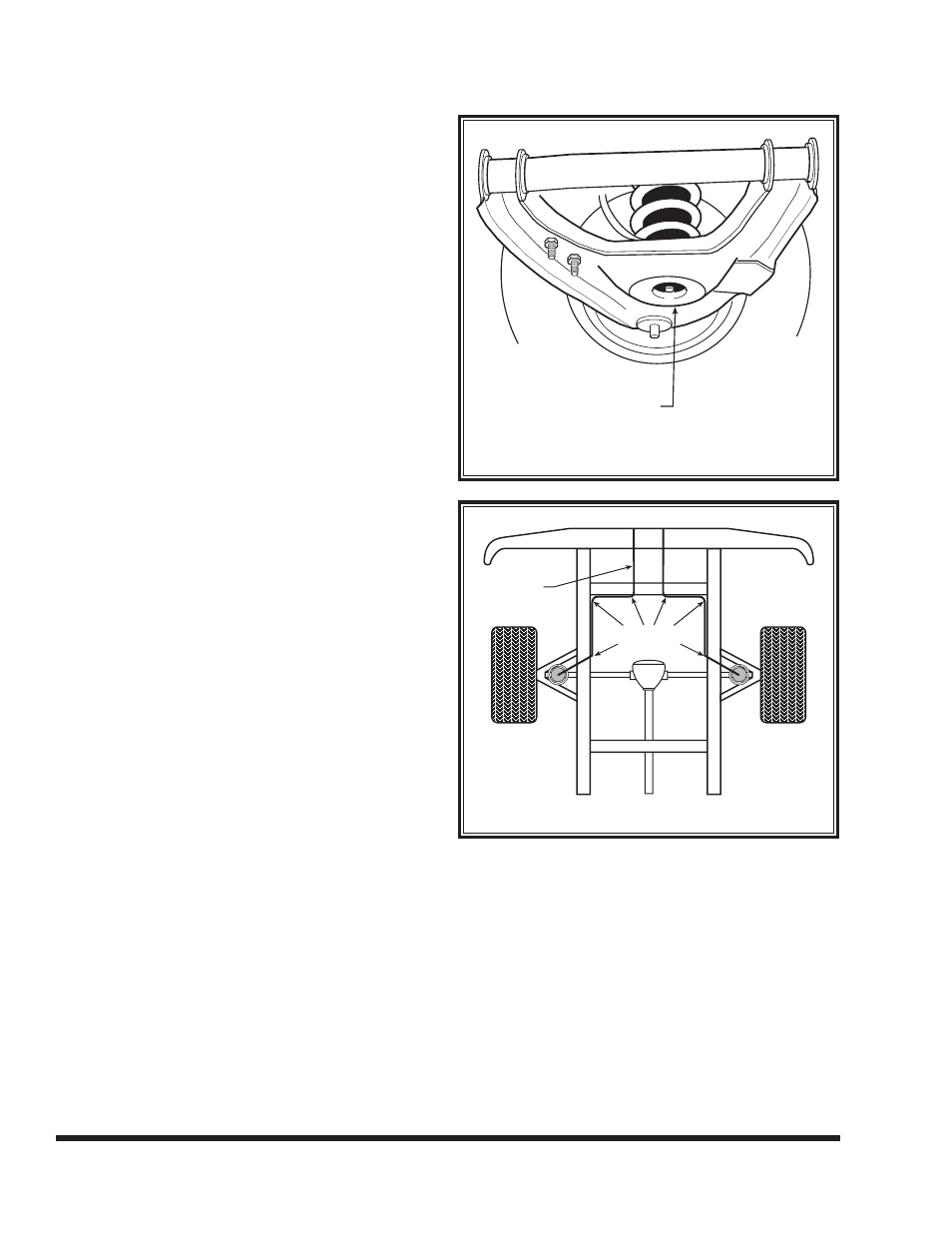
Exhaust the air from the air springs completely. Using
an electric drill and a 1-1/2" hole saw without a guide bit,
remove the center portion of the air spring in the hole in
the lower A-arm. Lubricate the hole in the lower A-arm
with a soap and water solution so that the air spring
can easily be pulled through the hole. Pull the air spring
through the hole in the A-arm with a pair of vise grips see
Figure “B”. Remove the existing support located at the
top of the coil spring.
STEP 3—PREPARE THE AIR SPRING
Remove the inflation valve capfrom the inflation valve
on the air spring. Using the valve cap on the push to-to-
connect inflation valve as a core tool, remove the inflation
valve core from the air spring. Hold it in the position as
shown in Figure “A”.
STEP 4—INSTALL THE AIR SPRING
Insert the air spring into the hole in the lower A-arm so
that the air inlet is oriented towards the ground see Figure
“A”. With the air spring still rolled tightly, work it through
the hole in the lower A-arm. Rotate the air spring while
pushing it through the hole in the A-arm. Push the air
spring completely through the hole. Allow the air spring
to expand to its normal shape once inside the coil spring,
see Figure “B”.
Using a blunt tire iron or socket extension, reach
through the top of the coil spring and push the air spring
downward. Insert the upper support through the coil
spring. Place the upper support so that the stud in the
upper spring seat inserts into the hole in the upper sup-
port,
see Figure "A".
Install the lower support in the same manner between
the bottom of the air spring and the lower spring seat,
see Figure “A”.
The hole in the lower support will provide access to
allow the inflation valve core to be reinstalled.
Reinstall the inflation valve core in the bottom of the
air spring. Use the valve cap of the push-to-connect infla-
tion valve to tighten the core.
COIL-RITE INSTALLATION PROCEDURE
FIGURE “B”
FIGURE “C”
Take all applicable safety precations when installing your air springs.
USING A HOLE SAW
,
CUT OUT THE CENTER
PORTION OF THE
AIR SPRING
NYLON
TIES
AIR LINE