2 tightening torques, 3 pressure/temperature diagram, Tightening torques – Richter KSEA/F Series Safety Valves User Manual
Page 4: Pressure/temperature diagram, Series ksea/f
Series KSEA/F
Page 4
9530-052-en
Revision 03
TM 7128
Edition 05/2008
Body identification:
The shell bears the following information:
valve size (Inlet x Outlet, inch)
pressure rating class
shell material
manufacturer's identification
cast number/foundry identification
arrow for direction of flow
1.2 Tightening
torques
All screws greased, tighten in diametrically opposite
sequence!
The tightening torques for pipe screws and body
screws mentioned must not be exceeded. For an
exception, see Section 8 flange connection valve /
pipe is leaking.
The following tightening torques are recommended:
Pipe screws, flanges to ASME B16.5, class 150
Flange nom.
diameter
Screws
Torque
[mm
]
[inch]
[ASME]
[in-lbs]
[Nm]
25
1
4 x ½“
70
8
50 2 4
x
5/8
“
220 25
80 3 4
x
5/8
“
400 45
100 4 8
x
5/8
“
310 35
150
6
8 x ¾“
710
80
Screws body / inlet nozzle
Valve type
Screws
Torque
[in-lbs]
[Nm]
KSEA/F 1”/2”
4 x N”-16 106 12
KSEA/F 2”/3”
4 x ½“-13
354
25
KSEA/F 3”/4”
8 x N”-16 177 20
KSEA/F 4”/6”
8 x N”-11 354 25
Hex. socket screws 914/1 of the bellows gasket
Valve type
Screws
Torque
[in-lbs]
[Nm]
KSEA/F 1”/2”
4 x 5/16“-18
89 10
KSEA/F 2”/3”
4 x 5/16“-18
106 12
KSEA/F 3”/4”
4 x 5/16“-18
106 12
KSEA/F 4”/6”
8 x 5/16“-18
89 10
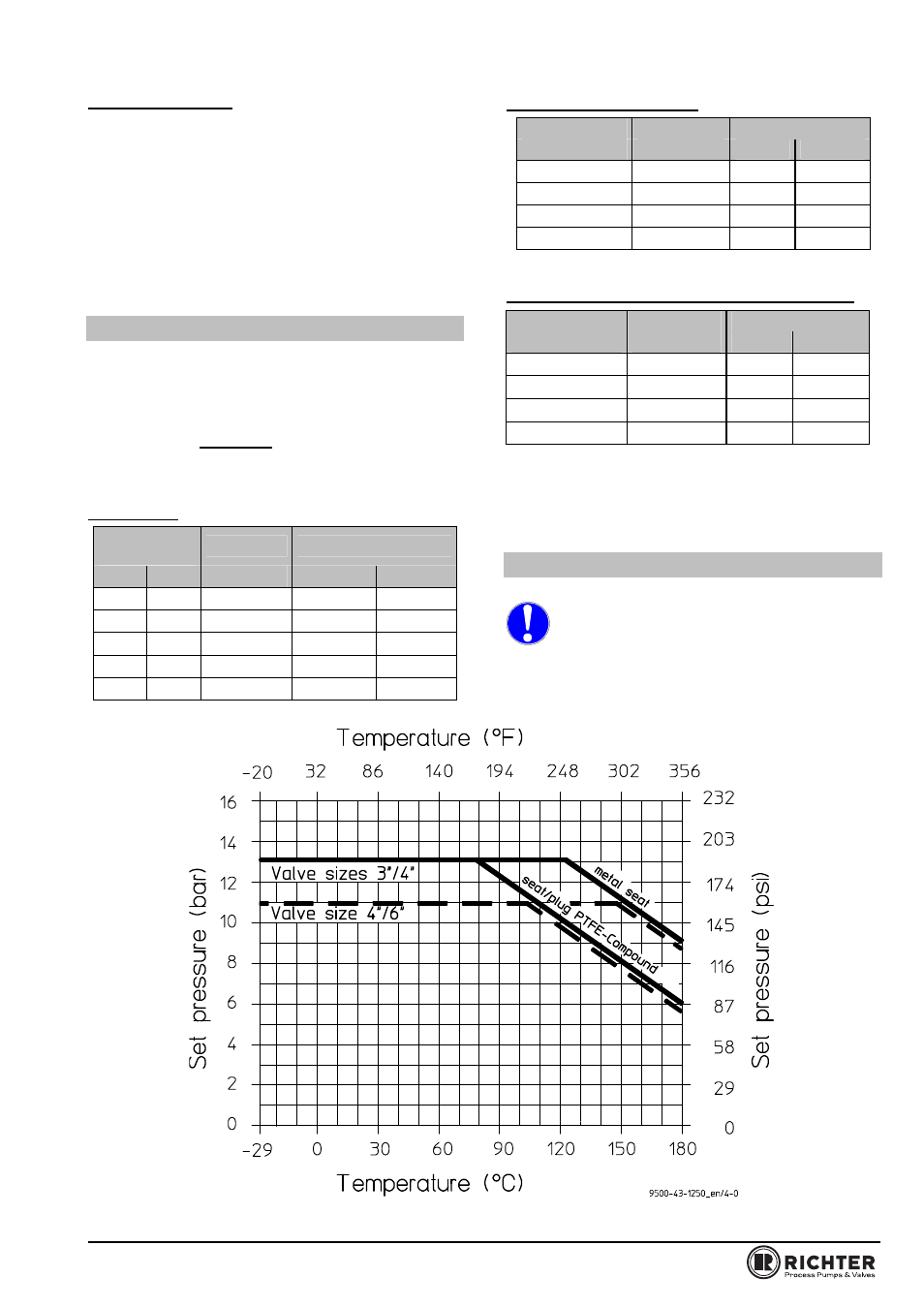
1.3 Pressure/temperature
diagram
When used in the minus temperature range,
the regulations applicable in the country in
question must be observed.
Max. permissible pressure/temperature for the body.