RCBS Rifle Bullet feeder - Dillon Conversion Kit User Manual
Page 6
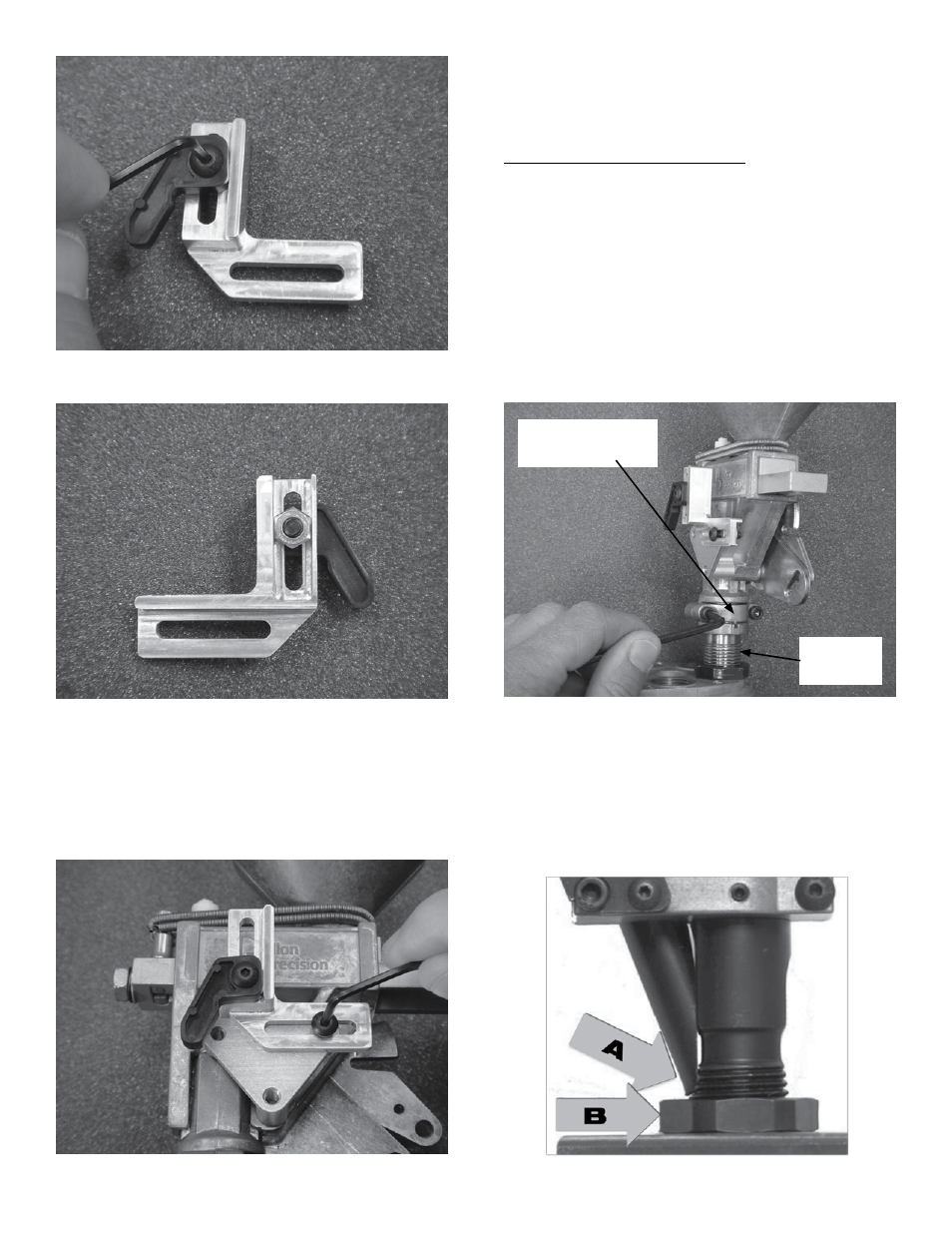
Photo 4
Photo 5
Next install this Cam Adjustment Bracket onto the
triangular PM Bracket as shown (Photo 6), using the
other 8-32 x 1/2” Long BHCS. Again, only slightly
tighten the BHCS for now.
Photo 6
INSTALLATION
Note: Reference the part schematic on page 11 for more
information.
Bullet Feed/ Seat Die Installation
First, tighten the setscrew on your PM Die Lock Ring
to keep it from moving. Next carefully detach the PM
Failsafe Rod from the Bellcrank Link Brackets (consult
your Powder Measure Manual for more information).
Next, remove your Powder Measure Assembly from the
Powder Measure Die by loosening the two SHCS 6-7
turns each using a 5/32” hex key (Photo 7). Slide the
notched-clamp collar outward and pull the PM off the
Die body. Finally, remove the PM Die from the
Die Plate.
Photo 7
Install the Bullet Feed/Seat Die Assembly into the
Die Plate at the station immediately after the Powder
Measure station. Screw it down until the Bullet Drop
Tube (A) on the back side of the Seat Die Assembly,
nearly contacts the Lock Ring (B) (Photo 8). Orient the
Seat Die Assembly so the Die’s window is facing front of
Press (Photo 10).
Photo 8
Notched-Clamp
Collar
PM Die
Body
6