Plumbing, Electrical connections, 2 plumbing 3.3 electrical – HF scientific 19998 Triple Validation Turbidimeter - 0-100 NTU User Manual
Page 12: Connections
TVT 1 (5/02)
6
Rev. 2.6 (.pdf)
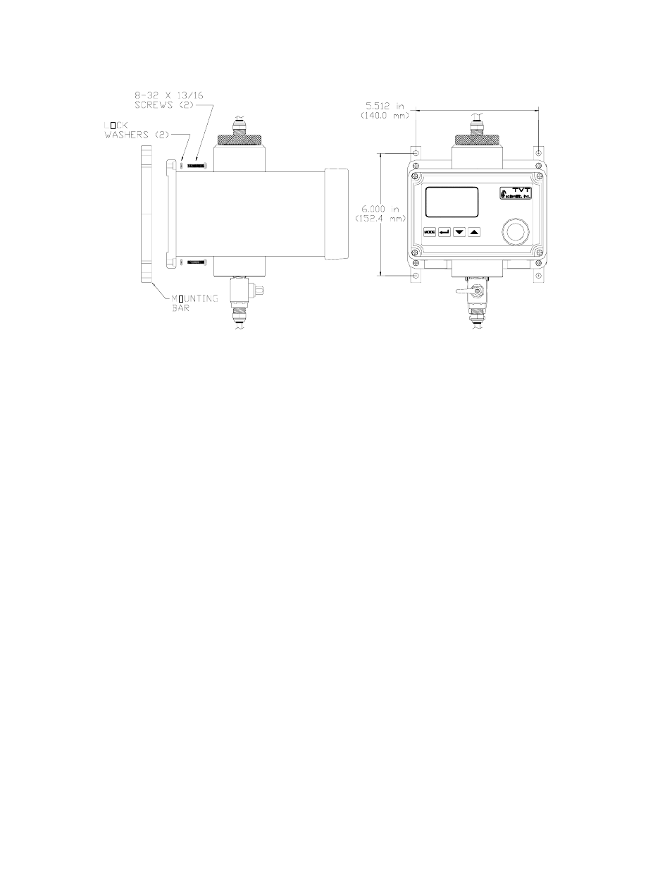
Figure 4: Use of the optional mounting bars to ensure isolation of the 4-20 mA output
3.2 Plumbing
The recommended plumbing for the instrument is shown in Figure 3. The instrument is
designed to limit the flow to the range of 0.4 – 0.6 liters/minute depending on the system
backpressure. Ensure that you supply the instrument with a process flow capable of
sustaining this level. Quick-connect fittings are supplied on the inlet and outlet of the
instrument; these fitting help speed up calibration procedures. These fittings will accept
0.25” OD x 0.170 ” ID tubing. Opaque tubing should be used if the tubing will be
exposed to sunlight
3.3 Electrical Connections
All of the electrical connections to the TVT except power, are made through cables
located on the lower section of the instrument. While facing the instrument, the right
connector is used for power supply (15 –18 VDC) connections. The middle cable is used
for the relay contact connections. The left cable provides the communication signals. As
you read the following sections, please refer to Figure 4 for clarification of the electrical
connections.
Please follow all local and government recommendations and methods for installation of
electrical connections to and between the instrument and other peripheral devices.
Note: Only qualified electricians should be allowed to perform the installation of the
instrument as it involves a line voltage that could endanger life.
Power: The input power connector is pre-assembled with either universal or a wall
mount power supply. Alternatively, if you can supply clean 15 –18 VDC to the system
you can do so without using a power adapter. In this instance the cable used for power
has 4 pins for connections. The connections are shown below: