HF scientific DRT-15CE Portable Turbidimeter User Manual
Page 12
DRT-15CE (5/10)
Page 4
5.0
RECORDER OUTPUT
The DRT-15CE has a 0-1 mA Recorder Output. The mA output jack is
located on right side of the chassis (refer to Figure 2). To use, connect the
1/8" miniplug provided to your recorder. Adjust R17 (pot nearest jack) to
obtain a full scale output compatible to a full scale reading on the DRT-
15CE. Once this adjustment is made, the DRT-15CE will always be set up
for this recorder. Use 10, 100 or 1000 NTU standard in appropriate range.
6.0
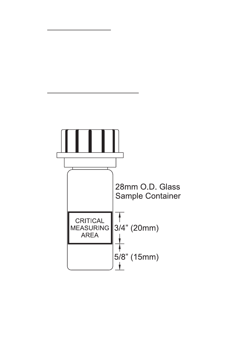
CRITICAL MEASURING AREA
The critical measuring area of the sample cuvette is a 3/4" wide band starting
5/8" above the bottom. Keep this area clean and free of scratches or
abrasion. Handle by the top part only. (See Figure 1).
Figure 1