HF scientific MicroTUV Online UV %Transmission Analyzer User Manual
Page 9
TUV (1/03)
REV. 0.2
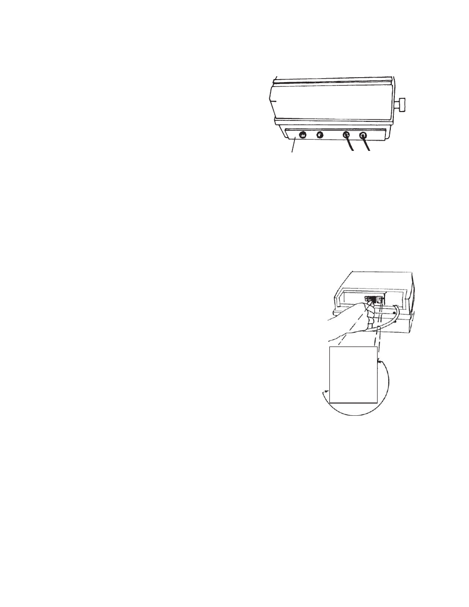
To remove the access cover:
Step 1) Loosen the two Analyzer clamping knobs.
Step 2) Swivel the Analyzer top forward, such that the
back is now facing you.
Step 3) Retighten the two Analyzer clamping knobs.
Step 4) Remove the 6 screws that retain the black
access cover.
Step 5) Remove access cover.
WARNING:
Do not restore power until the access cover
has been replaced and secured. When routing the cabling
for the following sections, allow enough excess cable length
to swivel the Analyzer upside down. Refer to figure 1 for
suggested cable routing. Do not over tighten the six screws
when replacing cover.
2.4.1 RS-485 Interconnecting Cable
The recommended interconnecting cable between the Analyzer and the
Sensor/Sampler is 2 conductor, shielded Belden M8451. (Not included.)
Refer to figure 4 for connection information.
Note: It is very important that a shielded cable is used.
2.4.2 Analyzer Power
The Analyzer power requirement is 40 VA at either 120 VAC or 240
VAC. The voltage setting of the Analyzer can be determined by
removing the access cover and looking at the fuse cartridge just to the left
of the power cord receptacle. The voltage printed next to the two
triangles that point toward each other indicates the selected voltage. To
change the input voltage, first remove the power cord. The fuse cartridge
can be removed by prying up with a flat blade screwdriver in the slot
provided. Pull the cartridge out, invert and then reinsert it. Refer to figure
2. To replace a blown fuse, remove the fuse cartridge as shown in figure
2. Replace only the fuse for your selected voltage. The triangle on the
fuse cartridge points to the fuse for the voltage selected. The correct fuse
ratings are 5 x 20 mm 1A fast acting for 120 VAC and 5 x 20 mm 1/2A
fast acting for 240 VAC. Refer to spare parts list, Section 6.4.
The power switch is located to the right of the power cord connection.
2.4.3
Analyzer D/A Outputs - Voltage & Current
The full-scale range of recorder outputs, both voltage and 4 - 20 mA are determined by the upper and lower
limits selected by the user. Please note that either 4 - 20 mA OR voltage output may be selected in the
DISPLAY PARAMETERS menu, but not both. Suggested scaling 0-100% T.
Twisted pair shielded cable, 22 AWG - 14 AWG is recommended. Tie the shield to the ground terminal at the
recorder end (Do not connect shield to TUV Analyzer).
Figure 1
Analyzer Cable Routing
RS-485
AC Power
Access
Figure 2
Changing Analyzer Voltage/Fuse
Page 3
USE ONLY WITH 250V
FUSES / EMPLOYER UNIQUEMENT AVEC
DES FUSIBLES DE 250V
110-120V
▼▼▼▼▼ ▲▲▲▲▲
220-240V
▲▲▲▲▲