Harrington Signal HS-3200 - Install Manual User Manual
Page 28
HS-3100/3200 Installation Manual
22
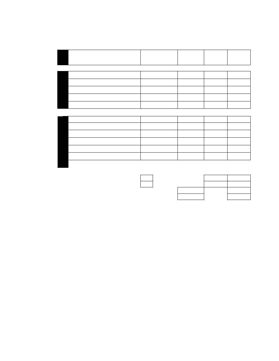
See next page for battery selection calculations.
Notes:
*
Each relay, when active, will draw 17mA. The alarm current will depend on how many relays
are programmed to activate on alarm.
**
Represents three (3) devices in alarm. For each additional device, add 5mA.
***
Alarm current depends on module configuration. Please refer to HSCTYB installation
Instructions for further detail.
**** If HS-3644 and HS-3434 are powered from AUX:
HS-3434 - 20mA Stby, 115mA Alarm (max)
HS-3644 - 30mA Stby, 70mA Alarm (max)
Add above currents for each annunciator or fiber optic modem, (i.e.) if 2 are present then multiply
above by 2.
Device
Standby
Total
Alarm
Total
Device Type
Qty.
Current
Standby
Current
Alarm
HS-3200 mainboard w/ LCD
1
x
110mA
110mA
175mA
175mA
display & primary power supply
Op
tion
al Int
ernal
Com
p
o
n
en
ts
HS3NC2 NAC output extender
x
10mA
_____ mA
65mA
_____ mA
HS3RL4 function relay o/p extender
x
5mA
_____ mA
17mA*
_____ mA
HS3LD8 8-zone LED annunciator
x
5mA
_____ mA
15mA**
_____ mA
HS3DL dual line DACT
x
40mA
40mA
65mA
65mA
HS3CTYB polarity reversal / municipal tie
x
20mA
20mA
_____ mA*** _____ mA***
Ad
dressab
le
In
pu
ts
Smoke detectors
x
_____ µA
_____ µA
_____ µA
_____ µA
Smoke detectors
x
_____ µA
_____ µA
_____ µA
_____ µA
Thermal detectors
x
_____ µA
_____ µA
_____ µA
_____ µA
Monitor modules
x
_____ µA
_____ µA
_____ µA
_____ µA
Control modules
x
_____µA
_____ µA
_____ µA
_____ µA
Fault isolator modules
x
_____ µA
_____ µA
_____ µA
_____ µA
See Appendix C for details on compatible addressable devices and their respective current draw.
Audible Notification Appliances (mA)
x
Visual Notification Appliances (mA)
x
AUX Power Load****
TOTAL (A):
TOTAL (B):