Installation instructions continued, Step 7: connecting electrical and supply tubing, Figure 7 – Bradley Smoker MG-2/TT User Manual
Page 12
Express® Lavatory System - MG-Series with TouchTime® Control
MG-2/TT
Installation Instructions
12
2/8/07
Bradley Corporation • 215-1480 Rev. E; EN 06-915
B BLACK
G BROWN
F BROWN
A BLACK
LEFT
BUTTON
LEFT
GRAY
RIGHT
GREEN
RIGHT
GRAY
RIGHT
BUTTON
LEFT
GREEN
VERNATHERM
THERMOSTATIC
MIXING VALVE
COMPRESSION
NUT
TRANSFORMER
S83-134
A BLACK
C BLACK
D BLACK
E BROWN
F BROWN
G BROWN
H BROWN
RIGHT GRAY
RIGHT GREEN
LEFT GREEN
B BLACK
LEFT GRAY
GREEN
SUPPLY
TUBE
RED
SUPPLY
TUBE
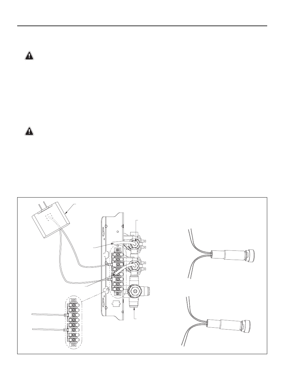
Figure 7
Installation Instructions continued . . .
Step 7: Connecting electrical and supply tubing
WARNING: MG-2/TT must be connected to 24 VAC Class II plug-in transformer provided.
Connection to 110 VAC may cause personal injury and/or damage to electronics.
Connection of leads other than shown may cause permanent damage to the switch.
1. Insert the two sprayhead supply tubes into the two solenoid tube connectors by loosening the
compression nut and firmly pushing the tubing into the connector until the tubes are fully seated,
then re-tighten the compression nut (hand-tight plus two full turns with a wrench) (see Figure 7).
2. Connect the wires per the wiring diagram shown below.
3. Align the mounting screws with slots on the frame. Valve bracket slides down to lock into place.
4. Turn on the water supply to the MG-2/TT Express® and check for leaks.
5. Turn on the electrical power, trigger the TouchTime® push buttons and check for proper function
(the timing is electronically controlled and set at 15 seconds).
IMPORTANT: The Vernatherm™ valve is NOT factory-preset. Upon installation, the valve
temperature must be checked and adjusted to assure delivery of safe water
temperature. Water in excess of 110°F (43°C) may cause scalding.
6. Check the temperature when approximately1.0 GPM water flow is reached and adjust if
necessary (the range of the valve is 95°F–115°F (35°C–43°C). To adjust the temperature, first
loosen the temperature locking nut with a wrench. Then using a blade screwdriver, turn the
adjustment stem counterclockwise to increase the temperature or clockwise to decrease the
temperature. Once desired temperature is reached, tighten the nut to prevent temperature change.
7. Reinstall panel to frame with the five Torx-head screws provided (see Figure 3 on page 8).
NOTE: Push button activation takes place only when released, (prevents “hold open” activation).