Tank installation, 2 x 10mm control surface centering, Clevis installation – E-flite Fury 15 DF BNF Basic User Manual
Page 6
EN
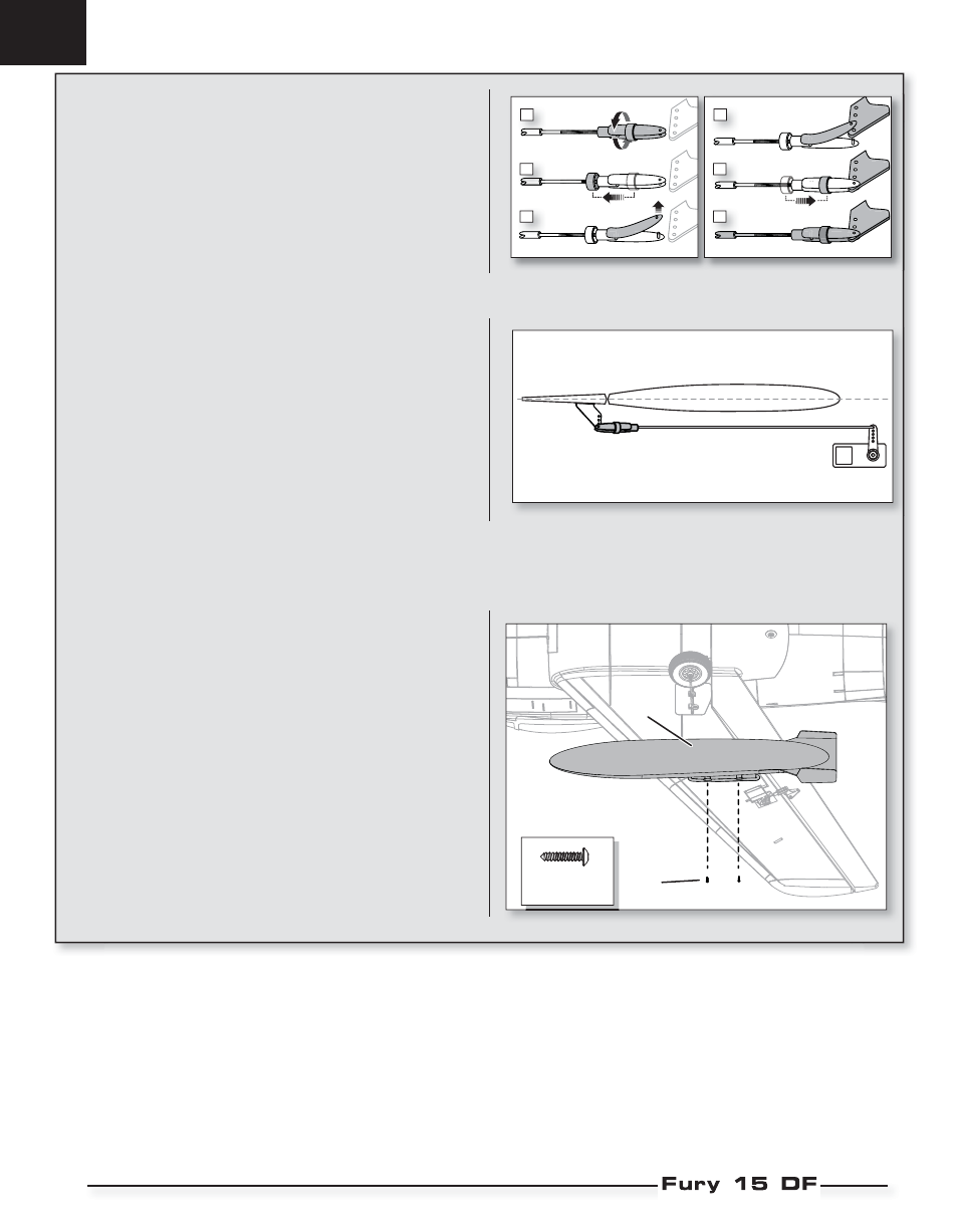
Tank Installation
1. If desired for scale appearance, install the tanks (A) in the wing mounts us-
ing 2 screws (B) each. The screws tighten correctly when they are installed
as shown.
Tip: For belly landing, remove or do not install the tanks.
When needed, disassemble in reverse order.
2 X 10mm
Control Surface Centering
After assembly, confi rm that the control surfaces are centered. If the control
surfaces are not centered, mechanically center the control surfaces by adjust-
ing the linkages.
IMPORTANT: DO NOT use sub-trim and trim to center the control surfaces. The
AS3X system requires sub-trim and trim set at 0.
If adjustment is required, turn the clevis on the linkage to change the length of
the linkage between the servo arm and the control horn.
After binding a transmitter to the aircraft receiver, set the trims and
sub-trims to 0, then adjust the clevises to center the control surfaces.
Clevis Installation
• Pull the tube from the clevis to the linkage.
• Carefully spread the clevis, then insert the clevis pin into the outer hole in
the control horn.
• Move the tube to hold the clevis on the control horn.
1.
2.
3.
4.
5.
6.
B
A
6