Control centering, Adjusting a clevis or ball link – E-flite Carbon-Z Scimitar BNF User Manual
Page 13
EN
Control Centering
• Make sure servo directions (reversing) on your transmitter are
correct. Ensure control surfaces move freely by performing a
Control Test.
• Make sure trim and sub-trims are set to zero.
• Make sure the servo arms are set to 90 degrees. If not, remove
a servo arm and put the arm in a spline position closest to the
90 degree position (perpendicular to the servo’s long axis). If 90
degrees exactly cannot be reached, use the sub-trim on your
transmitter to adjust the servo arm to the 90 degree position.
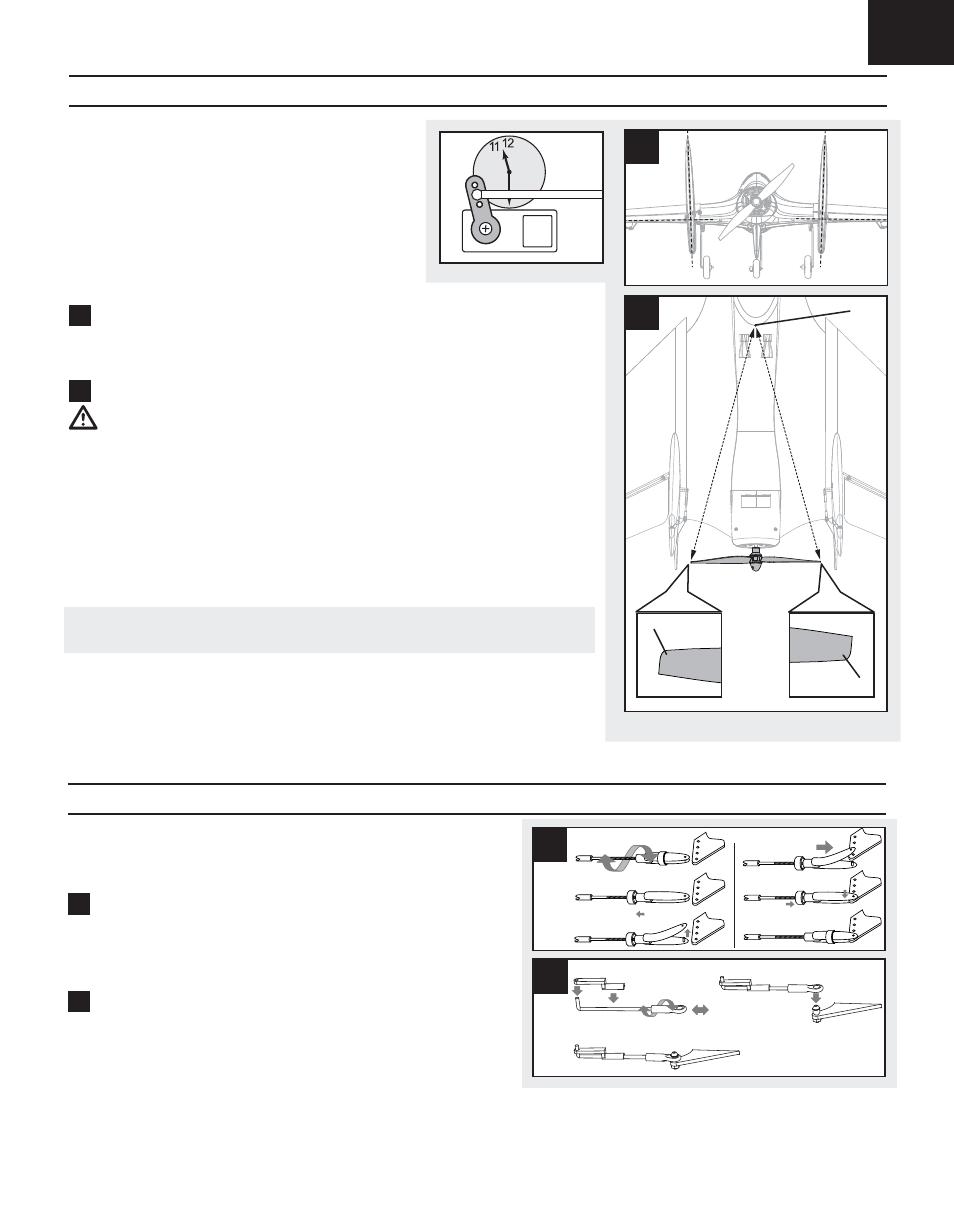
• The Vectored-Thrust (VT) servo arm is neutral at the 11:30
position (on a clock face) (A) when looking down from above
while standing at the rear of the airplane. This neutral position
gives the VT servo maximum throw in both directions.
1
Elevons and Rudder Centering
• The center for the elevons is alignment with the trailing edge of the fuselage between the rudders.
• The center of the rudders is alignment with the center of the vertical fi n to which the rudder
is attached.
2
Vectored-Thrust Centering
CAUTION: Always disconnect the fl ight battery from the ESC before handling the propeller or
injury could result.
• Turn the propeller to horizontal on the model.
• From above the model, measure from the right end of the propeller (leading edge tip (B) to the center
of the back of the canopy (C).
• Measure from the left end of the propeller (leading edge tip (D)) to the center of the back of the
canopy (C).
• These two measurements (A to B and B to C) are the same distance when the VT unit is centered.
Nose Gear Centering
• The center for nose steering occurs when the model follows a straight path while the rudder input is
at neutral.
TIP: When needed, turn the ball link or clevis until the control surface is at the center position
(up/down or left/right).
Refer to your transmitter’s manual for instructions about making adjustments to control surfaces,
Sub-Trim and Reverse.
1
2
C
B
D
After binding a transmitter to the model receiver, set trims and sub-trims to 0,
ensure servo arms are in the correct positions, then adjust clevises or ball links
to center the control surfaces.
Tip: Turn the clevis or ball link clockwise or counterclockwise on the linkage.
1
Adjusting a Clevis
• Pull the silicone tube from the clevis to the linkage.
• Carefully spread the clevis and put the clevis pin in a selected hole in the
control
horn.
• Move the tube to tighten the clevis on the control horn.
2
Adjusting a Ball link
• Connect the ball link to the ball installed on the control horn using pliers or
ball link pliers.
• Install the linkage in a hole in the servo arm using a link cover.
A
D
E
F
B
C
1
A
B
C
D
2
Adjusting a Clevis or Ball link
A
13