Watts SET User Manual
Solar hot water expansion tank, Installation instructions, Installation
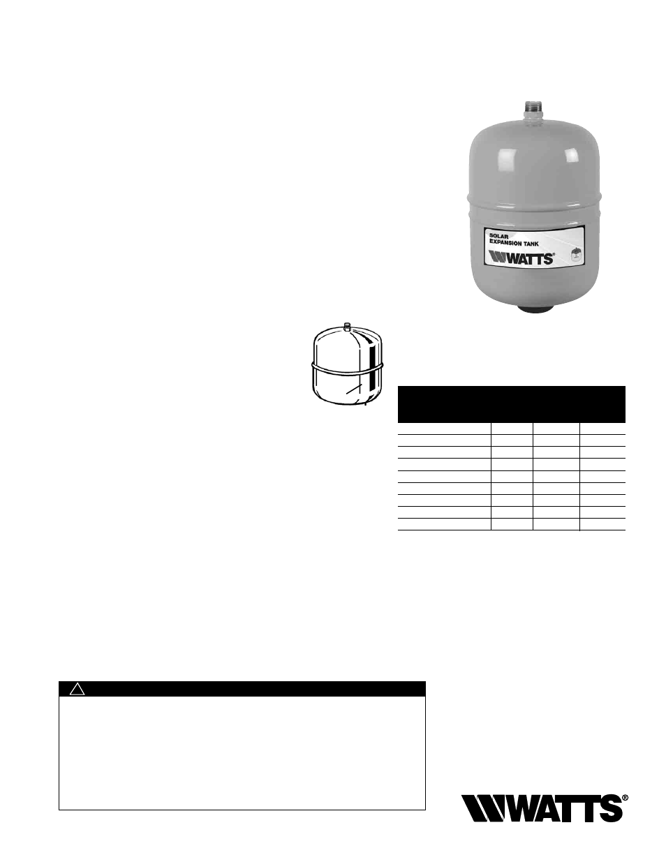
Models: SET-8, SET-18, SET-35
Solar Hot Water Expansion Tank
Installation Instructions
IS-SET
SET-8
SET-18
SET-35
Order No.
Order No.
Order No.
Description
0066616
0066617
0066618
Max. Pressure - psi
150
150
150
Max. Temp. - °F
240
240
240
Tank Volume - gal.
2.1
4.8
9.2
Tank Acceptance - gal.
1.05
2.4
4.6
Air Pre-charge - psi
20
20
20
Connections Size - in.
3
⁄
4
male
3
⁄
4
male
3
⁄
4
male
Diameter - in.
8.1
11.2
12.5
Length - in.
12.7
14.7
18.9
Weight - lbs.
5.7
9.5
15.4
Disclaimer: The manufacturer of this tank does not accept any liability or other
responsibility for personal injury or property damage resulting from improper use,
installation or operation of this tank or the system of which it is a part.
Notice: The expansion tank, piping and your connections may in time leak. Select
a location to install the expansion tank where a water leak will not damage the
surrounding area. The manufacturer is not responsible for any water damage in
connection with this expansion tank.
Improper installation, adjustment, alteration, service or maintenance can cause
property damage, serious bodily injury or death. Read instructions completely
before proceeding with installation. Only qualified personnel may install or service
this equipment in accordance with local codes and ordinances.
This Expansion Tank is designed and intended for water/solar fluid storage at a
maximum pressure of 150psi (10.3 bar) and a maximum temperature of 240°F
(116ºC). Any use other than for water/solar fluid or a sustained or instantaneous
pressure in excess of 150psi (10.3 bar) or 240°F (116ºC) is
UNSAFE and can cause
property damage, serious bodily injury or result in death.
WARNING
!
Installation
1. Use appropriate methods to determine correct pre-charge for expansion
tank. This is typically the same as or slightly lower than the solar loop ini-
tial pressure setting.
2. The normal tank pre-charge is 20psi. If this needs to be adjusted, follow
the instructions below.
Caution: Pre-charge prior to installation in the system. Do not adjust the air
pre-charge of the expansion tank with the system under pressure. The air
pre-charge should only be adjusted under zero pressure.
a. Unscrew the protective cap from the air inlet valve.
b. Using a tire pressure gauge, check the tank pre-
charge pressure.
c. If necessary, pressurize the tank to the proper setting
using a manual bicycle tire pump.
d. Replace the protective air cap.
3. Complete all high-pressure system tests prior to con-
necting expansion tank to system.
4. Install the expansion tank in the system.
Caution: There should not be a shutoff valve located between the expan-
sion tank (and the pressure relief valve) and the solar collector(s). This will
help maintain safe operating conditions should parts of the system need to
be isolated for any reason.
a. The weight of the expansion tank filled with water can be consider-
able. Therefore, it is important that, where appropriate, suitable bracing
(strapping, hanger, brackets) is used to support the tank and/or piping.
b. The expansion tank may be installed vertically (preferred method) or
horizontally. Caution: The tank must be properly supported in horizontal
applications.
c. This expansion tank, as all expansion tanks, may eventually leak. Do
not install without adequate drainage provisions.
5. Fill and purge system. Set system pressure appropriately.
Caution: Pre-charge prior to installation in the system. Do not adjust the air
pre-charge of the expansion tank with the system under pressure. The air
pre-charge should only be adjusted under zero system pressure.
If necessary, adjust the pressure reducing valve to the expansion tank pre-charge
as determined in Step 2.
Air Inlet Valve
Important!
• A pressure relief valve sized and installed in accor-
dance with local codes must be incorporated in
the systems requiring a combined temperature
and pressure safety relief valve. The temperature
and pressure safety relief valve should be sized
and installed in accordance with local codes.
• Never plug a safety Relief Valve.