Equipment specifications, Installation, Start-up – Watts OF1665-75 User Manual
Page 3
3
Specifications
Inlet Connection
2” PVC Union with Socket.
Outlet Connection 2” PVC Socket
Temperature
40° - 110°F
pH
6.5 to 8.5
Ferrous Iron, Max* 0.3 mg/L
Manganese, Max* 0.05 mg/L
Copper, Max*
1.3 mg/L
Water Pressure
15 min, 100 max (PSI)
Equipment Specifications
OneFlow
®
systems are complete, self-contained,
loaded with media, and ready to use. A simple
inlet and outlet connection is all that is required
for installation. Please review operating pressures,
temperatures and water chemistry limitations to
ensure compatibility.
Mechanical Specifications
MODEL
1465
1665
Dry Weight (lbs)
54
68
Service Weight (lbs)
350
420
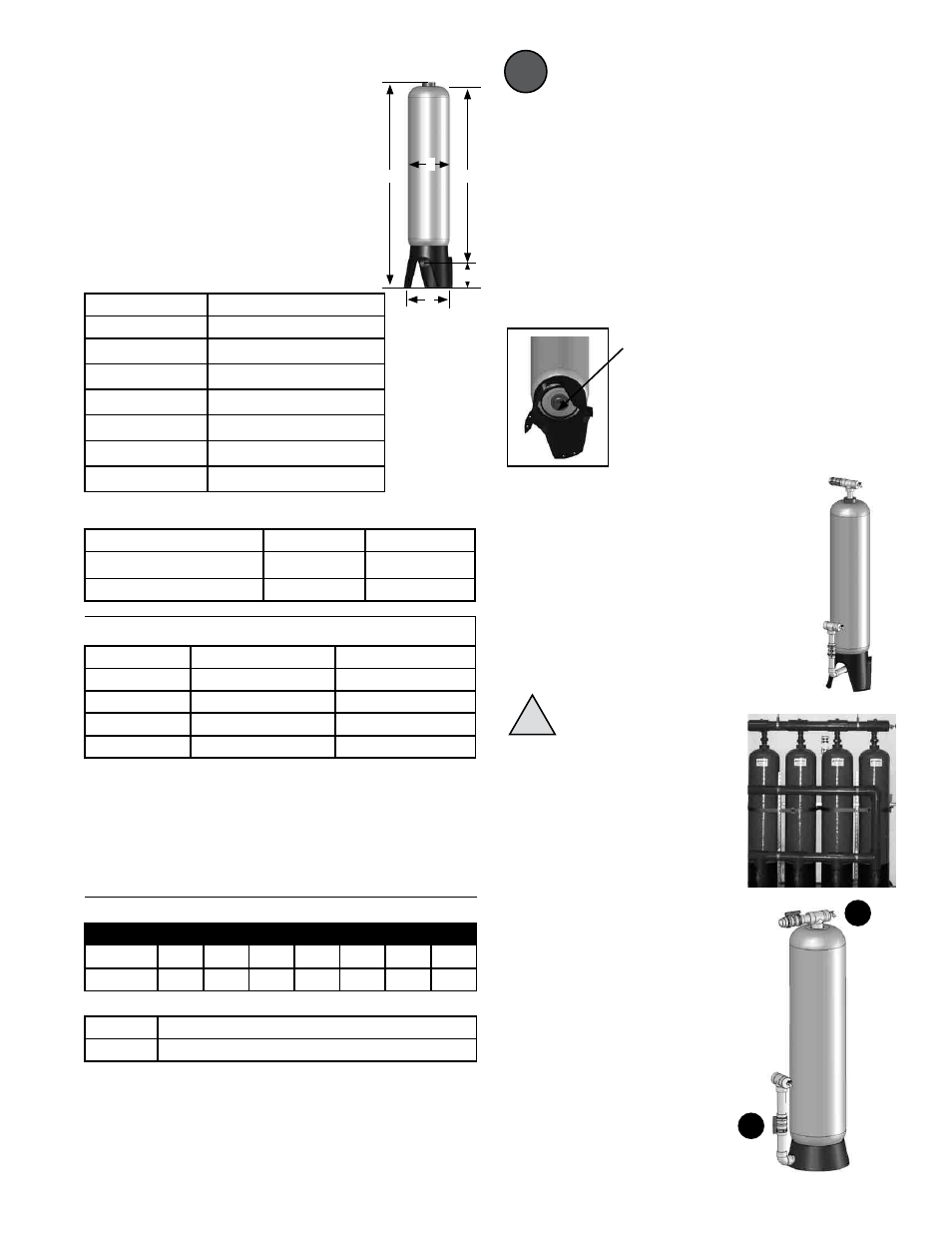
Dimensions
(nominal - inches)
a
17
17
b
14
16
c*
79
79
d
65
65
e*
10.25
10.50
* The overall height and the height of the inlet fitting varies due
to material variations and assembly tolerances. Please allow ad-
ditional clearance above the tank for making connections.
c
d
a
Installation
Tighten the Tank Bushings
Lay the tank down and check the bushings
on the inlet and outlet (bottom and top) of the
tank. It is common for them to loosen during
shipment. Tighten the bushings with a strap
wrench as needed
Install Piping
Connect the inlet and outlet plumbing according to
your preferences and any applicable local codes.
Include sample/drain ports with hose-bibb con-
nections on the inlet and outlet piping to facilitate
startup and service.
NOTE: We recommend the installation of a dual-union ball-valve
on the inlet and outlet to isolate the tank for servicing.
NOTE: A full bypass should be installed so that the full service
flow can be routed around the system as needed for servicing.
NOTE: The OneFlow
®
system operates in the Up-Flow mode
which is opposite of a conventional softener. The inlet is on the
bottom, the outlet on the top.
Important Notes!
!
i
Support the Piping
The full weight of the piping and
valves must be supported by uni-
strut, pipe hangers or other means.
The tank connections cannot sup-
port the weight of the piping. This
photo from a multi-tank system
installation shows properly supported
piping.
Tank bushing.
Rotate Clockwise
to tighten.
Start-Up
1
2
Connect a hose to the hose bibb on the
outlet of the tank. Run the hose to a drain.
Slowly / partially open the supply water
ball valve. Allow the tank to slowly fill with
water. When a steady stream of water ap-
pears at the drain, close the supply valve.
Open the inlet and outlet valves on the
system. Transfer the bypass valves from
Bypass to the Service position. Open
a nearby faucet downstream from the
OneFlow
®
system to relieve any air.
Check for leaks. Repair as needed.
The system is now ready for service.
MaximumServiceFlow(gpm)vs.Water
Temperature
ContinuousDutySystems:
System
40°F
45°F
50°F
55°F
60°F
65°F
70°F
14-65
40
44
48
50
50
50
50
16-65
45
51
56
59
63
69
75
IntermittentDutySystems:
14-65
50 GPM at all temperatures
16-65
75 GPM at all temperatures
* Intermittent duty is defined as less than 2 hours of Maximum
Flow per 24 hour period. Higher Flow rates can be achieved by
combining systems in an array.
e
b